Intel® CoreTM 2 Duo Processor and Intel ® Q35 Express Chipset Development Kit User’s Manual October 2007 Order Number: 318476-001US
INFORMATION IN THIS DOCUMENT IS PROVIDED IN CONNECTION WITH INTEL® PRODUCTS. NO LICENSE, EXPRESS OR IMPLIED, BY ESTOPPEL OR OTHERWISE, TO ANY INTELLECTUAL PROPERTY RIGHTS IS GRANTED BY THIS DOCUMENT.
Contents—Intel Core 2 Duo Processor and Intel Q35 Express Chipset Contents 1.0 About This Manual ..................................................................................................... 6 1.1 Content Overview................................................................................................ 6 1.2 Text Conventions ................................................................................................ 6 1.3 Glossary of Terms and Acronyms....................................
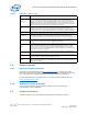
Intel Core 2 Duo Processor and Intel Q35 Express Chipset—Contents 6 7 8 9 10 11 12 13 14 15 16 17 18 19 20 21 22 23 24 Dual Channel (Interleaved) Mode Configuration with 4x DIMMs.......................................17 Single Channel (Asymmetric) Mode Configuration with 1x DIMM .....................................17 Single Channel (Asymmetric) Mode Configuration with 3x DIMMs ....................................18 Back-panel Connectors.....................................................................
Revision History—Intel Core 2 Duo Processor and Intel Q35 Express Chipset Revision History Date Revision Description October 2007 001 Initial release October 2007 Order Number: 318476-001US Intel® CoreTM 2 Duo Processor and Intel ® Q35 Express Chipset Development Kit User’s Manual 5
Intel Core 2 Duo Processor and Intel Q35 Express Chipset—About This Manual 1.0 About This Manual This user’s manual describes the use of the Intel® Q35 Express Chipset Development Kit. This manual has been written for OEMs, system evaluators, and embedded system developers. All jumpers, headers, LED functions, and their locations on the board, along with subsystem features and POST codes, are defined in this document.
About This Manual—Intel Core 2 Duo Processor and Intel Q35 Express Chipset is shown as 0FFH.) Decimal and binary numbers are represented by their customary notations (That is, 255 is a decimal number and 1111 1111 is a binary number). In some cases, the letter B is added for clarity. Units of Measure Signal Names 1.
Intel Core 2 Duo Processor and Intel Q35 Express Chipset—About This Manual Table 1. Definition (Sheet 2 of 2) Term Description nd ADD2 Card Advanced Digital Display Card – 2 Generation. This card provides digital display options for an Intel Graphics Controller that supports ADD2+ cards. It plugs into a x16 PCI Express* connector but uses the multiplexed SDVO interface. The card adds Video In capabilities to platform.
About This Manual—Intel Core 2 Duo Processor and Intel Q35 Express Chipset Table 2. Intel Literature Centers Location Telephone Number U.S. and Canada 1-800-548-4725 U.S. (from overseas) 708-296-9333 Europe (U.K.
Intel Core 2 Duo Processor and Intel Q35 Express Chipset—Development Kit Hardware Features 2.0 Development Kit Hardware Features This chapter describes the features of the Intel® Q35 Development Kit. These recommendations would largely apply to other designs incorporating Intel® Q35 chipset. This documentation should be used in conjunction with the datasheets, specification updates and platform design guides for the Intel® I/O Controller Hub 9 (ICH9) Family and the Intel® Q35 Express Chipset.
Development Kit Hardware Features—Intel Core 2 Duo Processor and Intel Q35 Express Chipset Figure 1. Board Features Reset button PCI Slot PCI Express x1 Slot Power Button SPI EEPROM (Secondary) Port 80 LED Display SPI EEPROM (Primary) PCI Express x16 Graphics Slot LGA775 Processor Socket Intel® I/O Controller Hub (ICH) SATA Port Intel® Q35 Memory Controller Hub (MCH) 2x2 Standard Power Supply 2x12 Standard Power Supply 2-DIMM per channel DDR2 667/800 (Channel-B) 2.
Intel Core 2 Duo Processor and Intel Q35 Express Chipset—Development Kit Hardware Features Figure 2. Intel® Q35 Express Chipset Development Kit block diagram 2.3 Development Kit Inventory Checklists This section describes major hardware items which should be available on this development kit. Table 3. Development Kit Hardware Items 1x 4-Layer Micro-BTX form factor (targeted dimensions: 10.5” x 10.
Development Kit Hardware Features—Intel Core 2 Duo Processor and Intel Q35 Express Chipset Table 4. Development Kit Board Specification 1 PCI Express x16, 2 PCIe x1, 1 PCI expansion slots 1394a • 1 front panel headers for support of 1 port • 1 back panel port Universal Serial Bus 2.0 • 2 front panel headers for support of 4 ports • 1 internal header for support of 2 ports • 6 back panel ports 6 SATA 3 Gb/sec ports (1 port used for eSATA) Table 5.
Intel Core 2 Duo Processor and Intel Q35 Express Chipset—Development Kit Hardware Features Table 6. Supported Intel Technologies (Sheet 2 of 2) Technology Features/support • Intel® Fast Memory Access Intel® Matrix Storage Technology (Intel® ICH8 DO only) • • Intel® High Definition Audio Table 7.
Development Kit Hardware Features—Intel Core 2 Duo Processor and Intel Q35 Express Chipset • Non-ECC DDR2 (667/800) • 512Mb, 1Gb and 2Gb technology • 4 DIMMs, 4GB maximum per channel, 8GB total memory • Dual channel (Interleaved) mode. This mode offers the highest throughput for real world applications. Dual channel mode is enabled when the installed memory capacities of both DIMM channels are equal.
Intel Core 2 Duo Processor and Intel Q35 Express Chipset—Development Kit Hardware Features Figure 4. Dual Channel (Interleaved) Mode Configuration with 2x DIMMs Figure 5 shows a dual channel configuration using 3 DIMMs. In this example, the combined capacity of the two DIMMs in Channel A equal the capacity of the single DIMM in the DIMM 0 socket of Channel B. Figure 5. Dual Channel (Interleaved) Mode Configuration with 3x DIMMs Figure 6 shows a dual channel configuration using 4 DIMMs.
Development Kit Hardware Features—Intel Core 2 Duo Processor and Intel Q35 Express Chipset Figure 6. Dual Channel (Interleaved) Mode Configuration with 4x DIMMs 2.5.2 Single Channel (Asymmetric) Mode Configurations Figure 7 shows a single channel configuration using 1x DIMM. In this example, only the DIMM 0 socket of Channel A is populated. Channel B is not populated. Figure 7. Single Channel (Asymmetric) Mode Configuration with 1x DIMM Figure 8 shows a single channel configuration using 3x DIMMs.
Intel Core 2 Duo Processor and Intel Q35 Express Chipset—Development Kit Hardware Features Figure 8. Single Channel (Asymmetric) Mode Configuration with 3x DIMMs 2.6 Back-Panel Connectors Figure 9 shows back-panel connectors for the development kit. Figure 9. Back-panel Connectors Side Speaker Out RJ-45 LAN Port 1394a Port Line-in Jack Rear Speaker Out USB Port (Total 6 Ports) 2.6.
Development Kit Hardware Features—Intel Core 2 Duo Processor and Intel Q35 Express Chipset Center/Subwoofer Speaker Out Jack (Orange) This audio jack is used to connect to center/subwoofer speakers in a 5.1 and 7.1channel audio configuration. Rear Speaker Out (Black) This audio jack is used to connect to rear speakers in a 5.1 and 7.1-channel audio configuration. Side Speaker Out (Gray) This audio jack is used to connect to side speakers for 7.1-channel audio configuration only. 2.6.
Intel Core 2 Duo Processor and Intel Q35 Express Chipset—Development Kit Hardware Features 2.7 Debug Features 2.7.1 Extended Debug Probe (XDP) The reference board provides a JTAG-compliant test access port (TAP) for attachment of an XDP connector. The XDP connector and associated circuitry enable the use of the ITP for the particular processor to interrupt the boot sequence and view processor status. The XDP connector is located on the backside of the board at location J2BC.
Development Kit Hardware Features—Intel Core 2 Duo Processor and Intel Q35 Express Chipset 2.7.4 Voltage Reference See Table 9 for details of the expected voltage levels for each voltage rail on the CRB. Table 9. Voltage Reference detail Voltage Rail 2.8 Expected Voltage Voltage Rail Expected Voltage VCC 5.0 V_1P25_CORE 1.25 VCC3 3.3 V_1P25_CL_MCH 1.25 +12V 12 V_1P25_PCIEXPRESS 1.25 -12V -12 V_SM 1.8 V_5P0_STBY\G 5.0 V_SM_VTT 0.9 V_3P3_STBY\G 3.3 V_3P3_CL 3.3 V_1P5_ICH 1.
Intel Core 2 Duo Processor and Intel Q35 Express Chipset—Development Kit Hardware Features 2.8.1 Jumper Functions Table 10 provides a list of the setting definitions for the Intel® CoreTM 2 Duo Processor and Intel ® Q35 Express Chipset Development Kit. Table 10.
Development Kit Hardware Features—Intel Core 2 Duo Processor and Intel Q35 Express Chipset Figure 13. Location for 1394a Header and USB Front Panel J24LB 1394a Header U1FW (USB Front Panel) Table 12. 1394a Header Pin Number 2.9 Definition 1 NDCD A- 2 NSIN A 3 NSOUT A 4 NDTR A- 5 GND 6 NDSR A- 7 NRTS A- 8 NCTS A- 9 NRI A- 10 No Pin SPI Removal / Installation Technique When removing or installing the SPI device, care must be taken to avoid damage to the SPI socket.
Intel Core 2 Duo Processor and Intel Q35 Express Chipset—Development Kit Hardware Features 2.9.1 SPI Device Removal To remove the SPI device from the socket, use a tweezer tip to gently pry one leg of the cap away from the socket. There is a small latch on the bottom of the leg of the cap. Once the cap latch is disengaged, the cap may be removed without causing damage to the latches on the ends.
Development Kit Hardware Features—Intel Core 2 Duo Processor and Intel Q35 Express Chipset Figure 15. SPI Device Installation 1. Place the fresh IC into the socket. Match pin 1. on the IC to pin 1 on the socket. 2. Close the cover. 3. Lock the cover with the hook.
Intel Core 2 Duo Processor and Intel Q35 Express Chipset—Setting Up and Configuring the Development Kit 3.0 Setting Up and Configuring the Development Kit This chapter discusses basic board set up and operation. Please refer to Chapter 2.0 for the board layout, jumper setting location and the component reference designator. 3.
Setting Up and Configuring the Development Kit—Intel Core 2 Duo Processor and Intel Q35 Express Chipset environment. Since the board is not in a protective chassis, the user is required to observe extra precautions when handling and operating the system. The board is a standard uBTX form factor and provides non-plated mounting holes with top and bottom ground rings. If the board is not going to be used in a chassis, standoffs are included for bench top use in the lab environment.
Intel Core 2 Duo Processor and Intel Q35 Express Chipset—Setting Up and Configuring the Development Kit Figure 18. Mounting the Standoff for BTX Heatsink 3.3 BTX Heatsink Setup with SRM This section describes BTX casing which uses “Support and Retention Module (SRM)” as shown in Figure 19. Note: SRM is not included in this development kits. Figure 19. Casing with “Support and Retention Module” 3.3.
Setting Up and Configuring the Development Kit—Intel Core 2 Duo Processor and Intel Q35 Express Chipset 1. Place the uBTX board on the Support and Retention Module (SRM) so that the holes A, B, C and D on the PCB line up with the corresponding locations on the SRM (see Figure 19). The board and SRM assembly should look like Figure 20. Figure 20. BTX board alignment on SRM 2. Place the heatsink on top of the processor. The heatsink should align with the holes on the SRM and board as shown below Figure 21.
Intel Core 2 Duo Processor and Intel Q35 Express Chipset—Setting Up and Configuring the Development Kit Figure 22. Tightening Heatsink on the SRM and Board 3.4 Board Setup and Configuration before Boot Follow the steps below to operate the board. Warning: Before starting, ensure the power supply is not connected to the board. Ensure a safe and static-free work environment before removing any components from their anti-static packaging.
Setting Up and Configuring the Development Kit—Intel Core 2 Duo Processor and Intel Q35 Express Chipset 2. Set jumpers to default positions. Refer to Section 2.8.1 for default positions. 3. Install the processor and ensure the 4-pin CPU fan power connector is installed on header shown in Figure 23. Figure 23. CPU Fan location 4-pin CPU Fan Power 4. Install the DDR2 DIMM in the Channel A Slot 0 connector.
Intel Core 2 Duo Processor and Intel Q35 Express Chipset—Setting Up and Configuring the Development Kit Figure 24. 2x12 Standard power supply and 2x2 power supply Power-on button 2x12 Standard power supply 2x2 Standard power supply 3.5 Post Codes Definitions The CRB BIOS writes progress and error codes to Port 80 during POST. These codes are defined below. 3.5.1 Normal Post Codes Uncompressed INIT code checkpoints Before D1 – Early chipset and SIO initialization. NMI disabled.
Setting Up and Configuring the Development Kit—Intel Core 2 Duo Processor and Intel Q35 Express Chipset D7 Restore CPUID value to register. Bootblock runtime module transferred to system memory. D8 Main BIOS runtime code is to be decompressed. D9 Copy main BIOS into system memory. E1-E8 OEM memory detection/configuration error. Range reserved for chipset vendors/OEMs. EC-EE Boot Block Recovery Code Checkpoints E0 Initialize Floppy Controller, DMA controller and interrupt controller.
Intel Core 2 Duo Processor and Intel Q35 Express Chipset—Setting Up and Configuring the Development Kit 08 Initialize CPU. The BAT test performed on KBC. Auto detection of KB and MS. C0 Early CPU Init Start. Disable cache and init local APIC. C1 Set up boot strap processor information. C2 Set up boot strap processor for POST. C5 Enumerate and set up application processors. C6 Re-enable cache for boot strap processor. C7 Early CPU Init Exit. 0A Initialize 8042 compatible keyboard controller.
Setting Up and Configuring the Development Kit—Intel Core 2 Duo Processor and Intel Q35 Express Chipset 60 Initialize NUM-LOCK status and program typematic rate. 75 Initialize INT-13 and prepare for IPL detection. 78 Initialize IPL devices controlled by BIOS and option ROMs. 7A Initialize option RMs. 7C Generate and write contents of ESCD in NVRAM. 84 Log errors encountered during POST. 85 Display errors and prompt for user response. 87 Execute BIOS setup if requested.
Intel Core 2 Duo Processor and Intel Q35 Express Chipset—Setting Up and Configuring the Development Kit Intel® CoreTM 2 Duo Processor and Intel User’s Manual 36 ® Q35 Express Chipset Development Kit October 2007 Order Number: 318476001US