PX875P Series Copyright All rights are reserved. No part of this publication may be reproduced, transmitted, transcribed, stored in a retrieval system or translated into any language or computer language, in any form or by any means, electronic, mechanical, magnetic, optical, chemical, manual or otherwise, without the prior written permission of the company. Brands and product names are trademarks or registered trademarks of their respective companies.
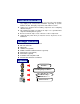
You have to know !!! 0 The images and pictures in this manual are for reference only and may vary slightly from actual product installation depending on specific hardware models, third party components and software versions. 0 Unplug your computer when installing components and configuring switches and pins. 0 This mainboard contains very delicate IC chips. Use a grounded wrist strap when working with the system. 0 Do not touch the IC chips, leads, connectors or other components.
PX875P Series Intel® 82875P & ICH5 Supports Socket 478 Intel® Pentium® 4 Processor User Manual Enabling Hyper-Threading for your computer system requires ALL of the following components z z z z ® ® CPU: An Intel Pentium 4 Processor with HT Technology Chipset: An Intel® Chipset that supports HT Technology BIOS: A BIOS that supports HT Technology must be enabled OS: An operating system that supports HT Technology For more information on Hyper-Threading Technology, go to: http://www.intel.
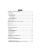
Contents CHAPTER 1. GETTING STARTED ............................................................1 INTRODUCTION.......................................................................................................... 1 SPECIFICATION .......................................................................................................... 2 QUICK CONTENT TABLE ........................................................................................... 5 CONFIGURATION ..........................................
PX875P PRO/ PX875P Chapter 1. Getting Started Introduction Congratulations on choosing the PX875P Series mainboard! The PX875P series includes the PX875P PRO (V2.0) and PX875P (V2.0). These are based on the 82875P Northbridge chipset and the ICH5 Southbridge chipset. It supports Intel® Pentium® 4 Processors with a FSB (Front Side Bus) frequency of 400/ 533/ 800 MHz. The PX875P series provides 4 DIMM slots using 184 pin DDR SDRAM with a total capacity of up to 4GB.
PX875P PRO/ PX875P Specification CPU: z Supports Socket 478 Pentium® 4 processor (Northwood/ Prescott) z Supports Hyper Threading Technology Speed: z 400/ 533/ 800 MHz Front Side Bus frequency z 33MHz, 32 bit PCI interface (PCI 2.2 compliant) z 66MHz AGP 3.0 compliant interface that supports 8X/4X data transfer modes (0.8V or 1.
PX875P PRO/ PX875P BUS Slots: z AGP slot (AGP3.0, 4X/ 8X) x 1 z 32-bit PCI bus slot x 5 Flash Memory: z Supports flash memory functionality z Supports ESCD functionality Hardware Monitor Function: z Monitors all fan Speeds z Monitors System Voltage Infrared: z Supports IrDA Version 1.0 SIR Protocol with a maximum baud rate of up to 115.2 Kbps z Supports SHARP ASK-IR Protocol with maximum baud rate of up to 57600 bps 3COM LAN Chip on board: (only for PX875P PRO V1.
PX875P PRO/ PX875P Universal Serial Bus: z Supports up to eight USB ports for USB interface devices z Supports USB 2.0 Enhanced Host Controller Interface (EHCI) and USB 1.1 Open Host Controller Interface (OHCI) Serial ATA facilities: z Compatible with SATA Spec 1.0 z Supports Serial ATA specification of 150 MB/sec transfers I/O facilities: z One multi-mode Parallel Port capable of supporting the following specifications: 1. Standard & Bi-direction Parallel Port 2. Enhanced Parallel Port (EPP) 3.
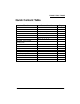
PX875P PRO/ PX875P Quick Content Table Function Content Location CPU Socket 478 U8 DIMM 1、2、3、4 DDR DIMM Slots ATX_12V、ATX_ PWR ATX Power Connector IDE Connectors、SATA Connectors IDE1/2、SATA1/2 FDC Connector AGP Slot PCI Slots CPU FAN、Chassis FAN、 Auxiliary FAN Front Panel Indicator Infrared Connector Front USB Headers Clear CMOS Jumper Case Open Warning Function Sony/Philips Digital Interface Conn.
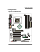
PX875P PRO/ PX875P Configuration Layout of PX875P PRO KB/MS ATX_12V USB/LAN ATX_PWR U8 Socket 478 PRT/COM U12 1 CPUFAN SOUND Intel 82875P DIMM4 Winbond W83627THF ALC 655 1 DIMM3 AUXFAN DIMM2 DIMM1 IDE2 IDE1 AGP PCI1 BAT1 PCI2 3COM LAN U19 2 1 PCI3 10 9 Intel ICH5 USB4 BIOS U21 JP1 1 1 SATA2 PCI4 SATA1 PCI5 FDC 1 2 1 USB2 USB3 1 2 1 2 1 FRONT AUDIO CD-IN SPDIF IrDA 2 1 CHASFAN 10 1 9 1 PWRLED SPEAKER 1 6 2 1 10 9 SW/LED CASE OPEN
PX875P PRO/ PX875P Layout of PX875P KB/MS ATX_12V USB ATX_PWR U8 Socket 478 PRT/COM U12 1 CPUFAN SOUND Intel 82875P 1 DIMM4 Winbond W83627THF ALC 655 DIMM3 AUXFAN DIMM2 DIMM1 IDE2 IDE1 AGP PCI1 BAT1 PCI2 U19 2 1 PCI3 10 9 Intel ICH5 USB4 BIOS U21 JP1 1 1 SATA2 PCI4 SATA1 PCI5 FDC 1 2 1 USB2 USB3 1 2 1 2 1 FRONT AUDIO CD-IN SPDIF IrDA 2 1 CHASFAN 10 1 9 1 PWRLED SPEAKER 1 7 2 1 10 9 SW/LED CASE OPEN
PX875P PRO/ PX875P Layout of PX875P PRO V2.
PX875P PRO/ PX875P Layout of PX875P V2.
PX875P PRO/ PX875P Hardware Installation This section will assist you in quickly installing your system hardware. Wear a wrist ground strap before handling components. Electrostatic discharge may damage your system components. CPU Processor Installation This mainboard supports Intel® Pentium® 4 processors using a Socket 478. Before building your system, we suggest you visit the Intel website and review the processor installation procedures. http://www.intel.com CPU Socket 478 Configuration Steps: 1.
PX875P PRO/ PX875P FAN Headers Three power headers are available for cooling fans, which play an important role in maintaining the ambient temperature in your system.
PX875P PRO/ PX875P To Enable Dual-Channel DDR, the following conditions must be met: 1.You must use either DIMM1 & DIMM3 together or DIMM2 & DIMM4 together or all four DIMM slots together. 2.You must use matching DIMM configurations between DIMM1 & DIMM3. You must use matching DIMM configurations between DIMM2 & DIMM4. z Same Density (128MB, 256MB, 512MB, etc.
PX875P PRO/ PX875P Back Panel Configuration PS/2 (optional) Mo use LAN Printer Port PS/2 Mouse Game Port (optional) LAN Printer Port Mic In Line In Sp ea ker Out USB PS/2 Keyboard COM1 PS/2 USB Keyboard COM2 Sp ea ker Out Mic In Line In (For V1.0) COM1 COM2 USB (For V2.0) PS/2 Mouse & PS/2 Keyboard Connectors: KB/MS The series mainboard provides a standard PS/2 mouse connector and PS/2 Keyboard connector.
PX875P PRO/ PX875P Serial and Parallel Interface Ports The series mainboard comes equipped with two serial ports and one parallel port on the back panel. These interface ports will be explained below. Printer Port COM1 COM2 Parallel Interface Port: PRT The parallel port on your system has a 25-pin, DB25 connector and is used to interface with parallel printers and other devices using a parallel interface.
PX875P PRO/ PX875P Front Panel Indicator: SW/LED、PWRLED、SPEAKER K B/MS U8 1 AU XFAN PCI1 S ocket 478 USB /L AN 1 CPU FAN SOU ND Winbond W83627HF PR T/C OM ALC 650 PCI2 PCI3 2 1 U12 Intel 82875P 2 1 A GP 10 9 2 1 USB 2 U SB3 USB 4 2 1 AT X_12V U19 Int e l IC H5 DIM M1 SATA1 SATA2 FD C P WRLE D2 1 S PE AKE R 1 CHASFAN 1 101 9 DIM M2 1 B AT 1 1 10 9 SW/LED DIM M3 DIM M4 AT X_PWR ID E2 IDE1 JP1 C AS E OP E N PWRLED PC I4 PCI5 3 3COM L AN 1 1 - 2 + U 21 BIO
PX875P PRO/ PX875P Connectors Floppy Disk Connector: FDC The series mainboard provides a standard floppy disk connector (FDC) that supports 360K, 720K, 1.2M, 1.44M and 2.88M floppy diskettes. This connector supports the floppy drive ribbon cables provided in the packaging. Hard Disk Connectors: IDE1-2/ SATA1-2 The series mainboard has a 32-bit Enhanced PCI IDE Controller that supports PIO Mode 0~4, Bus Master, Ultra ATA 33/ 66/ 100.
PX875P PRO/ PX875P Headers & Jumpers Front USB Headers: USB2/ USB3/ (USB4 for V1.0 only) The V1.0 series mainboard provide three USB headers (USB2/ 3/ 4) on the board allowing for 6 USB ports. And the V2.0 series mainboard provide two USB headers (USB2/ 3) on the board allowing for 4 USB ports. These attach to USB connectors embedded into the computer case or connected to a USB bracket (optional).
PX875P PRO/ PX875P Case Open Warning Jumper: CASE OPEN This connector is used to notify the user when the computer case has been previously opened. To configure this functionality, your computer case must be equipped with a “case open” cable which you need to attach to the CASE OPEN jumper. Also, you must enable CASE OPEN warning functionality in the BIOS setup utility. When your computer case is opened, your system will display alert messages upon boot up.
PX875P PRO/ PX875P Audio Connectors This mainboard provides three connectors as part of its audio Subsystem.
PX875P PRO/ PX875P S/PDIF Header: SPDIF S/PDIF (Sony/Philips Digital Interface) is an audio transfer file format, which provides high quality audio using optical fiber and digital signals. This mainboard is capable of delivering audio output and receiving audio input through the SPDIF header. One way you would use this header is by using an SPDIF & FRONT AUDIO bracket (optional) attached to your computer. This bracket will have two wires that you can attach to the SPDIF header and the FRONT_AUDIO header.
PX875P PRO/ PX875P Slots The slots in this mainboard are designed for expansion cards used to complement and enhance the functionality of the mainboard.
PX875P PRO/ PX875P Chapter 2. BIOS Setup Introduction This section describes PHOENIX-AWARD™ BIOS Setup program which resides in the BIOS firmware. The Setup program allows users to modify the basic system configuration. The configuration information is then saved to CMOS RAM where the data is sustained by battery after power-down. The BIOS provides critical low-level support for standard devices such as disk drives, serial ports and parallel ports.
PX875P PRO/ PX875P DRAM Support DDR (Double Data Rate) SDRAM (Synchronous DRAM) is supported. Supported CPUs This PHOENIX-AWARD™ BIOS supports the Intel® Pentium® 4 CPUs. Key Function In general, you can use the arrow keys to highlight items, press to select, use the and keys to change entries, press for help and press to quit. The following table provides more detail about how to navigate within the BIOS Setup program.
PX875P PRO/ PX875P Main Menu When you enter the PHOENIX-AWARD™ BIOS Utility, the Main Menu will appear on the screen. The Main menu allows you to select from several configuration options. Use the left/right arrow keys to select a particular configuration screen from the top menu bar or use the down arrow key to access and configure the information below.
PX875P PRO/ PX875P Main Menu Setup Configuration Options Item Options Description Date mm dd yyyy Set the system date. Note that the ‘Day’ automatically changes when you set the date. Time Hh: mm: ss Set the current time of the system. IDE Channel 0 Master Options contained in sub menu. Press to enter the sub menu. IDE Channel 0 Slave Options contained in sub menu. Press to enter the sub menu. IDE Channel 1 Master Options contained in sub menu.
PX875P PRO/ PX875P Advanced BIOS Features Removable Device Priority Select removable device priority. Just like floppy, LS120, ZIP-100, USB-FDD and USB-ZIP. Hard Disk Boot Priority Select hard disk boot priority. CD-ROM Boot Priority Select CD-ROM boot priority. First /Second/Third Boot Device Select the order in which devices will be searched in order to find a boot device.
PX875P PRO/ PX875P Advanced BIOS Features CPU L1 & L2 Cache Make CPU internal cache active or inactive. System performance may degrade if you disable this item. Options: Enabled (default)、Disable. Hyper-Threading Technology When you install a CPU include Hyper-Threading Technolong. And this item will allow you to enable or disabled the Hyper-Threading technology. Options: Disabled (default)、Enabled Quick Power On Self Test Allows the system to skip certain tests while booting.
PX875P PRO/ PX875P MPS Version Control For OS The 1.1 version is the older version that supports 8 more IRQs in the Windows NT environment. Choose the new 1.4 version for Windows 2000 and Windows XP. Options: 1.4 (default)、1.1 OS Select For DRAM > 64MB Select “OS2” only if you are running the OS/2 operating system with greater than 64MB of RAM. Options: Non-OS2 (default)、OS2 HDD S.M.A.R.T.
PX875P PRO/ PX875P DRAM RAS# to CAS# Delay This item allows you to select a delay time between the CAS and RAS strobe signals. It only applies when DRAM is written to, read from, or refreshed. This field is adjustable only when “DRAM Timing Selectable” is set to “manual”. This field is locked when “DRAM Timing Selectable” is set to “By SPD” and is automatically determined by the system. Options: 4、3、2 DRAM RAS# Precharge This item allows you to select the DRAM RAS# precharge time.
PX875P PRO/ PX875P P.A.T. Mode Allows user to enable “Performance Acceleration Technology” in FSB800/ DDR400 mode, using PAT can employ a specially configured “shortcut” or “by pass” when accessing memory, slicing several clock cycles from the access times and reducing conventional latency factors. Preliminary tests have shown that system performance and efficiency can be increased about 3% - 5%. If you want to set the “Turbo” or the “Ultra” options, please make sure your memory DIMMs can be overclock.
PX875P PRO/ PX875P Frequency/Voltage Control CPU Host Frequency (MHz) This item displays the CPU Host frequency . You can set it from XXX to 550 (or 255). The default depends on your CPU frequency. The default for this field depends on the CPU installed. CPU Clock Ratio 8X When you enable this field, the CPU clock ratio is fixed at “8X” and overrides the entry for the “CPU Clock Ratio” field (see “CPU Clock Ratio” field).
PX875P PRO/ PX875P Factory Default CPU Host Frequency Available Options 100 2.66X、2.50X (Debug) 133 Default (default)、2.00X、2.50X、 1.33X (Debug)、1.60X (Debug) 200 Default (default)、1.33X、1.60X、 2.00X、2.50X (Turbo) DDR Speed This item displays the current DDR memory speed. Spread Spectrum The Spread Spectrum function can reduce the EMI (Electromagnetic Interference) generated.
PX875P PRO/ PX875P AGP Frequency = 133 / 1.5 = 88.67 PCI Frequency = 133 / 3 = 44.33 SRC Frequency = 133 / 1 = 133.0 AGP Frequency This item displays the current AGP frequency. PCI Frequency This item displays the current PCI frequency. SRC Frequency This item displays the current SRC Frequency. Default CPU Voltage (Volt) This item displays the CPU default Voltage. CPU Voltage (Volt) This item allows you to adjust your CPU core voltage. Options: Default (default)、Default + 0.3V、Default + 0.
PX875P PRO/ PX875P Integrated Peripherals Init Display First With systems that have multiple video cards, this option determines whether the primary display uses a PCI slot or an AGP slot. Options: AGP (default)、PCI Slot OnChip IDE Device IDE HDD Block Mode Block mode is otherwise known as block transfer, multiple commands, or multiple sector read/write. Select the “Enabled” option if your IDE hard drive supports block mode (most new drives do).
PX875P PRO/ PX875P IDE Primary/Secondary/Master/Slave PIO The IDE PIO (Programmed Input / Output) fields let you set a PIO mode (0-4) for each of the IDE devices that the onboard IDE interface supports. Modes 0 to 4 will increase performance incrementally. In Auto mode, the system automatically determines the best mode for each device. Options: Auto (default)、Mode0、Mode1、Mode2、Mode3、Mode4.
PX875P PRO/ PX875P Serial ATA Port0/ 1 Mode This field determines the operating mode of the SATA ports. The options are determined by the “On-Chip Serial ATA” field. On-Chip Serial ATA – Combined Mode: When you set the “On-Chip Serial ATA” to “Combined Mode”, you must select one of the PATA channels to use with the SATA devices.
PX875P PRO/ PX875P Onboard LAN Boot ROM Decide whether to invoke the boot ROM of the onboard LAN chip. Options: Disabled (default)、Enabled Onboard I/O Chip Setup PWRON After PWR-Fail This field will determine whether your system will boot after restoring power after a power failure. If you select “On”, the system will boot whether or not the system was on before power failure. If you select “Former-Sts”, the system will be restored to the status before the power failure.
PX875P PRO/ PX875P RxD, TxD Active This item determines the RxD and TxD frequencies. This field only configurable if “UART Mode Select” is set to “ASKIR” or “IrDA”. Options: Hi / Lo (default)、Hi / Hi、Lo / Hi、Lo / Lo IR Transmission Delay This item allows you to enable/disable IR transmission delay. This field only configurable if “UART Mode Select” is set to “ASKIR” or “IrDA”. Options: Enabled (default)、Disabled UR2 Duplex Mode Select the transmission mode used by the IR interface.
PX875P PRO/ PX875P ECP Mode Use DMA Select a DMA Channel for the parallel port when using the ECP mode. This field is only configurable if “Parallel Port Mode” is set to “ECP”. Options: 3 (default)、1 Game Port Address (only for V1.0) Game Port I/O Address. Options: 201 (default)、209、Disabled Midi Port Address (only for V1.0) Midi Port Base I/O Address. Options: 330、300 (default)、290、Disabled Midi Port IRQ (only for V1.0) This determines the IRQ that the Midi Port will use.
PX875P PRO/ PX875P Power Management The Power Management Setup Menu allows you to configure your system to utilize energy conservation features as well as power-up/ power-down options. ACPI Suspend Type The item allows you to select the suspend type using the ACPI operating system. Options: S1 (POS) (default) Power on Suspend S3 (STR) Suspend to RAM S1 & S3 POS and STR Run VGABIOS if S3 Resume Select whether you want to run VGABIOS when the system wakes up from the S3 suspend function.
PX875P PRO/ PX875P 2. Max. Saving Maximum power management (only available for sl CPUs). Suspend Mode = 1 minute HDD Power Down = 1 minute 3. User Defined (default) Allows you to set each mode individually. When this option is enabled, each of the ranges are from 1 minute to 1 hour except for HDD Power Down, which ranges from 1 minute to 15 minute and includes a “disable” option. Note: If you select Min. or Max. Power Saving modes, the “HDD Power Down” value and the “Suspend Mode” value are both fixed.
PX875P PRO/ PX875P HDD Power Down When enabled, the hard disk drive will power down after a certain configurable period of system inactivity. All other devices remain active.
PX875P PRO/ PX875P Time (hh: mm: ss) Alarm You can choose the hour, minute and second the system will boot up. This field is only configurable when “RTC Wake Up” is set to “Enabled”. **Reload Global Timer Events** When a system goes into suspend mode, certain devices must be inactive for a period of time. Conversely, if any of those devices have any activity, the system will awaken. You can select the devices that will participate in suspend/power-on activity by configuring these fields.
PX875P PRO/ PX875P Hardware Monitor Case Open Warning If this function is set to “Enabled” and the case had been previously opened, the system will automatically display alert messages on the screen when you power on your computer. If this function is set to “Disabled”, the system will not show alert messages when you power on your computer even if the case had been previously opened. Options: Disabled (default)、Enabled Smart CPUFAN Temperature This item allows you to choose the CPUFAN temperature.
PX875P PRO/ PX875P Load Defaults Load System Default Settings Load System Default Settings. Load System Turbo Settings Load System Turbo Settings. Load CMOS From BIOS Load defaults from flash ROM for systems without batteries. Save CMOS To BIOS Save defaults to flash ROM for systems without batteries.
PX875P PRO/ PX875P Exit Menu Save & Exit Setup Save all configuration changes to CMOS (memory) and exit setup. A confirmation message will be displayed before proceeding. Exit Without Saving Abandon all changes made during the current session and exit setup. A confirmation message will be displayed before proceeding.
PX875P PRO/ PX875P Chapter 3: Software Setup Software List Category Platform Intel Chipset INF Windows 9X /ME /2000 /XP 3Com920 LAN Driver (for V1.0) Windows 9X /ME /2000 /XP Yukon V6.31 Lan Driver (for V2.0) Windows 9X /ME /2000 /XP Realtek Audio Driver Windows 9X /ME /2000 /XP Intel USB 2.0 Driver Windows 9X /ME PC-Cillin 2002 Windows 9X /ME /2000 /XP DirectX 9.
PX875P PRO/ PX875P 2. On the next screen, click the drivers that you want to install. (If you click the “Yukon V6.31 Lan Driver”, it will display the installation steps, please follow the description to complete the installation.) 3. If you click the “Intel USB 2.0 Driver” from the screen in step 2, it will display the screen as left. (Please follow the description to complete the installation.) 4. Back to the first page, click the “Tools” button and you can choose the software to install.
PX875P PRO/ PX875P Chapter 4: Troubleshooting Problem 1: No power to the system. Power light does not illuminate. Fan inside power supply does not turn on. Indicator lights on keyboard are not lit. Causes: 1. Power cable is unplugged. 2. Defective power cable. 3. Power supply failure. 4. Faulty wall outlet; circuit breaker or fuse blown. Solutions: 1. Make sure power cable is securely plugged in. 2. Replace cable. 3.Contact technical support. 4.
PX875P PRO/ PX875P Problem 4: System only boots from the CD-ROM. The hard disk can be read and applications can be used but booting from the hard disk is impossible. Causes: Hard Disk boot sector has been corrupted. Solutions: Back up data and applications files. Reformat the hard drive. Re-install applications and data using backup disks. Problem 5: Error message reading “SECTOR NOT FOUND” displays and the system does not allow certain data to be accessed.
PX875P PRO/ PX875P Problem 10: Keyboard failure. Causes: Keyboard is disconnected. Solutions: Reconnect keyboard. Replace keyboard if you continue to experience problems. Problem 11: No color on screen. Causes: 1. Faulty Monitor. 2. CMOS incorrectly set up. Solutions: 1. If possible, connect monitor to another system. If no color appears, replace monitor. 2. Call technical support. Problem 12: The screen displays “C: drive failure.” Causes: Hard drive cable not connected properly.
PX875P PRO/ PX875P Appendix I: Over Clocking Important Before you attempt to overclock your system, we strongly recommend that you obtain a thorough understanding of all of the variables, procedures, and the potential risks associated with overclocking. Because we cannot control of all of the possible variables that exist (i.e. memory, AGP card, user configurations, cooling apparatus etc), we cannot assume responsibility from damage to any components of your system due to overclocking.
PX875P PRO/ PX875P How to configure your new frequencies. As mentioned you must enter the BIOS Setup Utility in order to begin configuring overclocking parameters. After you reboot your system, press the “Del” key when prompted to enter the BIOS Setup Utility. The parameters for overclocking will be found in the “Advanced” screen as part of the “Frequency/Voltage Control” section.
PX875P PRO/ PX875P AGP/PCI/SRC Speed Setting This item determines the AGP, PCI and SRC frequencies (speed settings). You can set these frequencies using the supplied BIOS options. One of the options available to you is “Auto, Auto, Auto”. Using the “Auto, Auto, Auto” option will instruct the system to automatically calculate these frequencies based on the factory default “CPU Host Frequency” setting, the current “CPU Host Frequency” setting and the formulas in the table below.
PX875P PRO/ PX875P Testing Even though you have configured your overclocking options and have successfully booted to your operating system, it doesn’t mean that you have successfully overclocked your system. Testing is an equally important aspect of overclocking and you must stress your configurations thoroughly to ensure stability. It is better to discover that your system locks up during testing rather than experiencing the same while editing valuable information.
PX875P PRO/ PX875P Example: This example shows you how to overclock the CPU Internal Clock, DDR frequency and FSB frequency for an Intel based mainboard. Note that the options that are supplied with your version of the BIOS may vary slightly. The example is for reference only. Given: Mainboard: CPU: DDR: Intel based mainboard Pentium 4 (1.
PX875P PRO/ PX875P Appendix II: Super 5.1 Channel Setup 1. After into the system, click the audio icon from the Windows screen. 2. Click Speaker Configuration button, you can see the screen like the picture below. 3. You can choice 2, 4 or 6 channels by your speakers. 2 Channels 4 Channels 6 Channels Super 5.1 Channel Audio Effect This mainboard comes with an ALC655 Codec which supports high quality 5.1 Channel audio effects.
PX875P PRO/ PX875P Appendix III: Installing a Windows® OS to the SATA HDD Please refer to the steps below to install a windows® OS to the SATA HDD 1. Make sure that the “On-Chip Serial ATA” option is set to “ Combined Mode ” in the BIOS Setup Utility. BIOS Setup Utility -> Integrated Peripherals Æ OnChip IDE Device Æ On-Chip Serial ATA Æ “Combined Mode” 2. Make sure that either the “Serial ATA Port0 Mode” or “Serial ATA Port1 Mode” option is set to “Primary Master” in the BIOS Setup Utility.