USER'S MANUAL Of Intel H55 Express Chipset Based M/B for Intel LGA 1156 Processors PMH55 MB Rev.: 1.0 Manual Rev.: EG100 Release date: January, 2010 Trademark: * Specifications and Information contained in this documentation are furnished for information use only, and are subject to change at any time without notice, and should not be construed as a commitment by manufacturer.
Environmental Protection Announcement Do not dispose this electronic device into the trash while discarding. To minimize pollution and ensure environment protection of mother earth, please recycle.
TABLE OF CONTENT ENVIROMENTAL SAFETY INSTRUCTION................................................................iii USER’S NOTICE .........................................................................................................iv MANUAL REVISION INFORMATION .........................................................................iv COOLING SOLUTIONS ..............................................................................................
Environmental Safety Instruction z Avoid the dusty, humidity and temperature extremes. Do not place the product in any area where it may become wet. z 0 to 40 centigrade is the suitable temperature. (The figure comes from the request of the main chipset). z Generally speaking, dramatic changes in temperature may lead to contact malfunction and crackles due to constant thermal expansion and contraction from the welding spots’ that connect components and PCB.
USER’S NOTICE COPYRIGHT OF THIS MANUAL BELONGS TO THE MANUFACTURER. NO PART OF THIS MANUAL, INCLUDING THE PRODUCTS AND SOFTWARES DESCRIBED IN IT MAY BE REPRODUCED, TRANSMITTED OR TRANSLATED INTO ANY LANGUAGE IN ANY FORM OR BY ANY MEANS WITHOUT WRITTEN PERMISSION OF THE MANUFACTURER. THIS MANUAL CONTAINS ALL INFORMATION REQUIRED FOR THE UTILIZATION OF THIS MOTHERBOARDS TO MEET THE USER’S REQUIREMENTS. BUT IT WILL CHANGE, CORRECT AT ANY TIME WITHOUT NOTICE.
Chapter 1 Introduction of Intel H55 Express Chipset Motherboards 1-1 Features of Motherboard The Intel H55 Express chipset based motherboard series are based on Intel H55 Express chipset technology which supports the innovative Intel LGA 1156 socket Intel® Core™ i7, Intel® Core™ i5(Lynnfield & Clarkdale), Core™ i3 and Pentium® Processor.
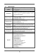
to read the detailed descriptions of these value added product features, please get them in the coming section. 1-1.1 Special Features of motherboard CPU Smart Fan--- The Noise Management System It’s never been a good idea to gain the performance of your system by sacrificing its acoustics. CPU Smart Fan Noise Management System is the answer to control the noise level needed for now-a-day’s high performance computing system.
1-2 Specification Spec Design Chipset z z z CPU Socket Description factor, 4 layers U-ATX form 23.0cmx24.5cm Intel H55 Express Chipset blue PCB size: supports the innovative Intel LGA 1156 socket Intel®, Core™ i7, Core™ i5(Lynnfield & Clarkdale), Core™ i3 and Pentium® Processor. Memory Sockets Expansion Slots z z z z DDRIII module slot x 4 Support 4pcs DDRIII 1066/DDRIII 1333 memory modules expandable to 16GB. Support dual channel function 1pcs PCI-Express2.
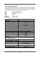
1-3 Performance List The following performance data list is the testing result of some popular benchmark testing programs. These data are just referred by users, and there is no responsibility for different testing data values gotten by users (the different Hardware & Software configuration will result in different benchmark testing results.) CPU: HDD: VGA: BIOS: MEMORY: VGA DRIVER: Intel CPU 3.07GHZ 08# WesternDigtal 160GB SATA onboard VGA R1.00 Apacer 2G1333 06.14.14.10.
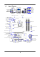
1-4 Layout Diagram Coaxial SPDIF_OUT PS/2 Mouse Connector Line-IN VGA Connector RJ-45 LAN Line-OUT CS-OUT HDMI Connector PS/2 Keyboard Connector Optical SPDIF_OUT RS-OUT SS-OUT DVI Connector KB/MS Power On (JP1) USB Connectors MIC-IN CPU FAN1 PS2 KB/MS Port (KB1) G.P.I LED Coaxial/Optical SPDIF_OUT Connectors HDMI Connector VGA Connector Over DVI Connector CPU Socket DDRIII Slot x 4 ATX 12V Power Connector SYSFAN2 JP2 USB Connector ATX Power Conn.
Jumpers Jumper JBAT JP1 JP2/ JP3 Name CMOS RAM Clear KB/MS Power On Enabled/Disabled USB Power On Enabled/Disabled Description 2-pin Block 3-pin Block 3-pin Block Connectors Connector ATXPWR ATX12V J1 Name ATX Power Connector ATX 12V Power Connector Large 4-pin Power Connector Description 24-pin Block 8-pin Block 4-pin Block KB1 PS/2 Mouse & PS/2 Keyboard Connector 6-pin Female USB from UL1 and USB1 RJ 45 LAN from UL1 AUDIO SATA~SATA6 SPDIF_ Out SPDIF_ Out2 USB 2.
Chapter 2 Hardware Installation WARNING! 2-1 Turn off your power when adding or removing expansion cards or other system components. Failure to do so may cause severe damage to both your motherboard and expansion cards. Hardware installation Steps Before using your computer, you had better complete the following steps: 1. Check motherboard jumper setting 2. Install CPU and Fan 3. Install System Memory (DIMM) 4. Install Expansion cards 5. Connect IDE Front Panel /Back Panel cable 6.
(2) KB/MS Power on Function Enabled/Disabled: JP1 JP1 JP1 1-2 Closed KB/MS Power ON Disable (Default) 2-3 Closed KB/MS Power ON Enabled Keyboard/Mouse Power On Setting (3) USB Power On function Enabled/Disabled: JP2/JP3 JP2 / JP3 1-2 closed (Default) JP2/ JP3 USB Power On Disable 2-3 closed USB Power On Enabled USB Power-On Setting 2-3 Installing CPU 2-3-1 Glossary Chipset (or core logic) - two or more integrated circuits which control the interfaces between the system processor, RAM, I/O devises
Processor - the "central processing unit" (CPU); the principal integrated circuit used for doing the "computing" in "personal computer" Front Side Bus Frequency - the working frequency of the motherboard, which is generated by the clock generator for CPU, DRAM and PCI BUS. CPU L2 Cache - the flash memory inside the CPU, normal it depend on CPU type. 2-3-2 About Intel LGA 1156 CPU Socket This motherboard provides an 1156-pin DIP, LGA 1156 Land Grid Array socket, referred to as the LGA 1156 socket.
2-3-3 1. LGA 1156 CPU Installation Guide 2. Press down the level and move it to the left side Please make sure that CPU socket is facing towards you and the level is on you left hand side. to make sure it is freed from the hook and then open it upwards about 135 degree. 3. Open the level upwards about 135 degree and the 4. Remove the plastic protective cap from the socket. (Put it to the original place if CPU is not installed. Do not touch the metal contact point of the CPU socket).
6.Put down the load plate in the direction shown above. 7. Press down the load level and move it rightwards make sure it is locked under the notch. 2-3-4 Intel Reference Thermal Solution Assembly Align the fastener with the hole 1. Put the heat sink vertically above the 2. Revolve the four fasteners CP-installed socket and make sure to align counter-clockwise direction. the four fasteners with four holes around the socket. in the Motherboard 3. Press down two fasteners down in the 4.
2-4 Install Memory This motherboard provides four 240-pin DDR III DUAL INLINE MEMORY MODULES (DIMM) socket for DDR III memory expansion available to maximum memory volume of 16GB DDRIII SDRAM. Valid Memory Configurations Bank 240-Pin DIMM PCS Maximum Capacity DIMM1 DIMM2 DIMM3 DIMM4 Total DDR III 1066/ DDR III1333 DDR III 1066/ DDR III1333 DDR III 1066/ DDR III1333 DDR III 1066/ DDR III1333 System Memory (Max 4GB) X1 X1 X1 X1 4 4GB 4GB 4GB 4GB 16GB Recommend DIMM Module Combination: 1. 2. 3.
Installation Tips: Open the two plastic clips of memory slots then push down the module vertically into the slot. See to it that the hole of the module fit into the notch of the slot; The two plastic clips will automatically close if the memory module is fitted in a proper way. We suggest that priority given to DIMM1 and DIMM3 in multi-DIMM installation. System won’t start when you only install memory DIMM in DIMM2 and DIMM4. 2-5 Expansion Cards 2-5-1 Procedure For Expansion Card Installation 1.
2-5-3 PCI Express Slot The H55 Express chipset based motherboard series offer two PCI-Express2.0 x16 graphics slots. With PE1 being PCI Express 2.0 x16by16 lane slot and PE3 being PCI Express 2.0 x16by4 lane slot. These two graphics slots are fully compatible with the latest AMD CrossFireX Technology to guarantee the fully operational Multi-GPUs graphics function and avoid the possible installation error.
3. Be careful with the position for the pin you would like to set up. 4. Keep straight to force the CF Bridges plug into both sides of CrossFire Tech Supported VGA Cards.
ROW1 ROW2 ROW1 ROW2 PIN Pin 1 Pin 1 20-Pin 24-Pin ROW1 ROW2 1 3.3V 3.3V 2 3.3V -12V 3 GND GND 4 5V Soft Power On 5 GND GND 6 5V GND 7 GND GND 8 Power OK -5V 9 +5V (for Soft Logic) +5V 10 +12V +5V 11 +12V +5V 12 +3V GND ** If you are using a 20-pin power plug, please refer to Figure1 for power supply connection. Power plug form power supply and power connectors from motherboard both adopt key design to avoid mistake installation.
(3) Large 4-Pin Power Connector:J1 The connectors are 4-pin connector that supports extra 12V / 5V power to your system (4) PS/2 Mouse & PS/2 Keyboard Connector: KB1 The connectors are for PS/2 keyboard and PS/2 Mouse. (5) USB Port connector: USB port fromUL1, USB1 The connectors are 4-pin connectors that connect USB devices with the 480 Mbit / sec data transfer rate to the system board.
(8) Serial-ATA2 Port connectors: SATA1~SATA6 These connectors support the provided Serial ATA and Serial ATA2 IDE hard disk cable to connect the motherboard and serial ATA2 hard disk drives. (9) SPDIF Out connectors: SPDIF_OUT/SPDIF_OUT2 The SPDIF output is capable of providing digital audio to external speakers or compressed AC3 data to an external Dolby digital decoder. Use this feature only when your stereo system has digital input function.
JW FP PWRBTN GND PWRBTN PWRLED Pin 1 VCC5 PWRLED PWR LED (3) Speaker connector: SPEAK This 4-pin connector connects to the case-mounted speaker. See the figure below. (4) Power LED: PWR LED The Power LED is light on while the system power is on. Connect the Power LED from the system case to this pin. (5) IDE Activity LED: HD LED This connector connects to the hard disk activity indicator light on the case.
(9) CD Audio-In Headers (4-pin): CDIN CDIN are the connectors for CD-Audio Input signal. CD-ROM CD-Audio output connector. Please connect it to CDIN 4 1 CD Audio-In Headers GND IR1 +5VX (10) IR infrared module Headers (5-pin): IR1 This connector supports the optional wireless transmitting and receiving infrared module. You must configure the setting through the BIOS setup to use the IR function.
(12) SPDIF Out header: HDMI_SPDIF The SPDIF output is capable of providing digital audio to external speakers or compressed AC3 data to an external Dolby digital decoder. Use this feature only when your stereo system has digital input function. GND HDMI_SPDIF_OUT 1 2 HDMI_SPDIF Header N.C +3.3V D1+ GND USB+5 WI-FI1 D1- (13) WI-FI Header: WI-FI 1 This header supports WI-FI Function. Connect the wireless local area network adapter to this header.
2-7 Starting Up Your Computer 1. After all connection is made, close your computer case cover. 2. Be sure all the switch are off, and check that the power supply input voltage is set to proper position, usually in-put voltage is 220V∼240V or 110V∼120V depending on your country’s voltage used. 3. Connect the power supply cord into the power supply located on the back of your system case according to your system user’s manual. 4. Turn on your peripheral as following order: a. Your monitor. b.
Chapter 3 Introducing BIOS The BIOS is a program located on a Flash Memory on the motherboard. This program is a bridge between motherboard and operating system. When you start the computer, the BIOS program will gain control. The BIOS first operates an auto-diagnostic test called POST (power on self test) for all the necessary hardware, it detects the entire hardware device and configures the parameters of the hardware synchronization.
3-3 The Main Menu Once you enter AMI BIOS Setup Utility, the Main Menu (Figure 3-1) will appear on the screen. The Main Menu allows you to select from 12 setup functions and 2 exit choices. Use arrow keys to select among the items and press to accept or enter the sub-menu. Figure 3-1 Standard BIOS Features Use this Menu for basic system configurations. Advanced BIOS Features Use this menu to set the Advanced Features available on your system.
Change User Password This entry for setting User password Save Changes and Exit Save CMOS value changes to CMOS and exit setup. Discard Changes and Exit Abandon all CMOS value changes and exit setup. 3-4 Standard BIOS Features The items in Standard CMOS Setup Menu are divided into several categories. Eachcategory includes no, one or more than one setup items. Use the arrow keys to highlight the item and then use the <+> or <-> and numerical keyboard keys to select the value you want in each item.
3-5 Advanced BIOS Features Boot Sector Virus Protection The selection Allow you to choose the VIRUS Warning feature for IDE Hard Disk boot sector protection. If this function is enabled and someone attempt to write data into this area, BIOS will show a warning message on screen and alarm beep. Disabled (default) No warning message to appear when anything attempts to access the boot sector or hard disk partition table.
3-5-1 CPU Features C1E Function This should be enabled in order to enable or disable the “Enhanced Halt State”. The optional settings are: Enabled; Disabled. Hardware Prefetcher For UP platforms, leave it as Enabled. For DP/MP servers, it may use to tune performance to the specific application. The optional settings are: Enabled; Disabled. Adjacent Cache Line Prefetch For UP platforms, leave it as Enabled. For DP/MP servers, it may use to tune performance to the specific application.
Intel(R) SpeedStep (tm) tech The optional settings are: Enabled; Disabled. Disable: Disable GV3; Enabe: Enable GV3. InteL(R) TurboMode tech Turbo mode allows processor cores to run faster than marked frequency in specific condition. Intel(R) C-STATE tech CState: CPU idle is set to C2/C3/C4. 3-6 Advanced Chipset Features The Advanced Chipset Features Setup option is used to change the values of the chipset registers. These registers control most of the system options in the computer.
3-7 Integrated Peripherals Configure SATA#1 as Press Enter to select the SATA type. The optional settings are: IDE; AHCI and Disabled. SATA#1 IDE Configuration The optional settings are: Compatible and Enhanced. SATA#2 IDE Configuration The optional settings are: Disabled and Enhanced. Onboard PCIE Lan Controller Use this item to enable or disable onboard PCIE Lan controller. Onboard PCIE Lan BootROM The optional settings are: Disabled; Enabled. USB Functions The optional settings are: Disabled; Enabled.
3-8 Power Management Setup The Power Management Setup allows you to configure your system to most effectively save energy saving while operating in a manner consistent with your own style of computer use. ACPI Version Features The optional settings are: ACPI v1.0; ACPI v2.0; ACPI v3.0. Enable RSDP pointers to 64-bit Fixed SYSTEM Description Tables. Di ACPI version has some. ACPI APIC Support Include ACPI APIC table pointer to RSDT pointer list.
High Performance Event Timer The optional settings are: Enabled; Disabled. Resume On RTC Alarm Use this item to disable or enable RTC to generate a wake event. 3-9 Miscellaneous Control Palette Snooping The optional settings are: Enabled; Disabled. Enable: inform the PCI device that an ISA graphics devices is installed in the system so the card will function correctly. 3-10 PC Health Status This section shows the Status of you CPU, Fan, and Warning for overall system status.
CPUFAN1 Mode Setting Press enter to select CPU Mode setting, the optional settings are: Manual Mode; Thermal Cruise Mode; Speed Cruise Mode; Smart FAN III Mode. 3-11 User Overclok Settings Linear PCIEX Clock Use this item to set Linear PCIEX clock in the range of 100 to 200. CPU Diff AMP The optional settings are: 700mV; 800mV; 900mV; 1000mV. PCIEX Diff AMP The optional settings are: 700mV; 800mV;900mV;1000mV. CPU Clock Skew The optional settings are: Default; 100ps~1500ps.
Use this item to set CPU VTT voltage from 1.140Vto 2.247V. The default value is 1.176v. DRAM Voltage Select Use this item to set DRAM voltage from 1.538V (Default) to2.204V. The default value is 1.589v. CPU AGX Voltage Select The optional settings are: Auto, +50mV~+350 mV. If set the voltage too high (+250mV~+350 mV), the color of the word will changed. NOTICE! The voltage in BIOS settings is only for reference, for different motherboards, voltage settings may be different.
3-13 Load Optimal Defaults/ Load Standard Defaults Load Optimal Defaults When you press on this item, you get a confirmation dialog box with a message similar to: Pressing loads the default values that are factory settings for optimal performance system operations. Load Standard Defaults When you press on this item, you get a confirmation dialog box with a message similar to: Pressing loads the default values that are factory settings for stable performance system operations.
Chapter 4 Driver Installation Check your package and there is A MAGIC INSTALL CD included. This CD consists of all DRIVERS you need. MAGIC INSTALL Supports WINDOWS XP/ Vista/ 7 Insert CD into your CD-ROM drive and the MAGIC INSTALL Menu should appear as below. If the menu does not appear, double-click MY COMPUTER / double-click CD-ROM drive. From MENU you may make as selections: 1. 2. 3. 4. 5. 6. 7.
4-1 INF: Install Intel INF Chipset System Driver Windows XP Windows XP 64 Windows VISTA/ VISTA 64/ 7 x86/ 7 x64 36
4-2 IMSS: Install Intel IMSS Chipset System Driver Windows XP Windows XP 64 Windows VISTA/ VISTA 64/ 7 x86/ 7 x64 37
4-3 VGA: Install VGA Driver Windows XP Windows XP 64 Windows VISTA/ VISTA 64/ 7 x86/ 7 x64 38
4-4 LAN: Gigabit Ethernet LAN Driver Windows XP Windows XP 64 Windows VISTA/ VISTA 64/ 7 x86/ 7 x64 39
4-5 SOUND: Install Audio Codec Driver Windows XP Windows XP 64 Windows VISTA/ VISTA 64/ 7 x86/ 7 x64 40
4-6 AHCI: Install Intel AHCI Driver Windows XP Windows XP 64 Windows VISTA/ VISTA 64/ 7 x86/ 7 x64 41
4-7 User’s Manual 4-8 How to Update BIOS STEP 1. Prepare a bootable disk. (You may make one by click START click RUN type SYS A: click OK) STEP 2. Download upgrade tools and the latest BIOS files of the motherboard from official website and then make a copy of it to your bootable floppy disk after decompressing these files STEP 3. Insert the disk into A: start your computer and then type in “A:\xxxxxx.BAT”(xxxxxxx being the file name of the latest BIOS ) STEP 4. Type Enter to update and flash the BIOS.
4-9 G.P.I. Function LED Display PWS_LED4 PWS_LED3 PWS_LED2 PWS_LED1 All LED off or glitter. It means the motherboard in the G.P.I mode. CPU works with the low power consumption. PWS_LED4 PWS_LED3 PWS_LED2 PWS_LED1 Three LED off or glitter. It means the motherboard is working on partial power saving mode. (The LED off indicate the relative power phase working with idle mode). PWS_LED4 PWS_LED3 PWS_LED2 PWS_LED1 Three LED on. It means the motherboard is working on partial power saving mode.