PM945GC (V2.0) Copyright All rights are reserved. No part of this publication may be reproduced, transmitted, transcribed, stored in a retrieval system or translated into any language or computer language, in any form or by any means, electronic, mechanical, magnetic, optical, chemical, manual or otherwise, without the prior written permission of the company. Brands and product names are trademarks or registered trademarks of their respective companies.
PM945GC (V2.0) Intel® 945GC & ICH7 Support Socket 775 Intel® CoreTM 2 Duo/ Pentium® D/ Pentium® 4/ Celeron® D/ Celeron® Processor (The power consumption for the aforementioned processors must be rated at 65W or less.
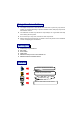
Things You Have To Know 0 The images and pictures in this manual are for reference only and may vary from the product you received depending on specific hardware models, third party components and software versions. 0 This mainboard contains very delicate IC chips. Always use a grounded wrist strap when working with the system. 0 Do not touch any IC chip, lead, connector or other components.
Table of Contents CHAPTER 1. GETTING STARTED .................................................... 1 INTRODUCTION ....................................................................................................... 1 SPECIFICATION ....................................................................................................... 2 CONFIGURATION .................................................................................................... 5 Layout of PM945GC (V2.0)...............................
Mainboard PM945GC(V2.0) Chapter 1. Getting Started Introduction Thanks for choosing PM945GC(V2.0) Mainboard. It is based on Intel® 945GC Northbridge chipset and Intel® ICH7 Southbridge chipset. In addition, it also supports integrated Graphics Media Accelerator 950 for onboard graphics feature.
Mainboard PM945GC(V2.0) Specification CPU: Support Socket 775 Support Intel® CoreTM 2 Duo/ Pentium® D/ Pentium® 4/ Celeron® D/ Celeron® Processors (The power consumption for the aforementioned processors must be rated at 65W or less.
Mainboard PM945GC(V2.0) FDD Connector: Supports one FDD connector to set up to two floppy disk drives Supports 360KB/ 720KB/ 1.2MB/ 1.44MB/ 2.88MB IDE Connector: One IDE connector Supports up to two IDE devices Supports Ultra ATA 33/66/100 Supports high capacity hard disk drives Serial ATA II Connector: Four SATA II connectors Supports SATA 2.
Mainboard PM945GC(V2.
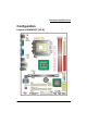
Mainboard PM945GC(V2.0) Configuration Layout of PM945GC (V2.
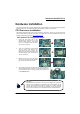
Mainboard PM945GC(V2.0) Hardware Installation This section will assist you in quickly installing your system hardware. Wear a wrist ground strap before handling components. Electrostatic discharge may damage the system’s components. CPU Processor Installation This mainboard supports Intel® CoreTM 2 Duo/ Pentium® D/ Pentium® 4/ Celeron® D/ Celeron® Processors using a Socket 775. Before building your system, we suggest you to visit the Intel website and review the processor installation procedures.
Mainboard PM945GC(V2.0) FAN Headers: CPUFAN, SYSFAN1, SYSFAN2 There are three fan headers available for cooling fans. The cooling fans play an important role in maintaining ambient temperatures in your system. The CPUFAN header is attached with a CPU cooling fan. The SYSFAN1 and SYSFAN2 headers are attached with other cooling fans. CPUFAN SYSFAN1/ SYSFAN2 Attention You can avoid damaging your CPU due to high temperatures with proper cooling equipment.
Mainboard PM945GC(V2.0) How to enable Dual-Channel DDRII: 1. These mainboards provide Dual-Channel functionality for the two DIMM sockets. Enabling Dual-Channel can significantly increase your data access rates. DIMM1 and DIMM2 share one channel. 2. For enabling Dual-Channel, you have to install two memories in the DIMM sockets at the same time; according to the definition by Intel, once one channel of the memory capacity is the same with the other channel, then Dual-Channel will be enabled. 3.
Mainboard PM945GC(V2.0) Back Panel Configuration PS/2 Mouse & PS/2 Keyboard Ports: KB/MS This mainboard provides a standard PS/2 mouse port and a PS/2 keyboard port. The Serial Port: COM1 This mainboard provides a serial port COM1 on your back panel, and is used to connect mice, modem and other peripheral devices. Through this port, you can also transfer data from your computer hard disk drive to other computers.
Mainboard PM945GC(V2.0) Audio Ports: SOUND This mainboard provides three audio ports, the Mic, Line-in and Line-out. These are the standard audio ports that provide basic audio function. Line-In (Blue) This port is for audio input and connects to external audio devices such as CD player, tape player, etc. When the multi-channel audio system is enabled, this port will output audio for the rear speakers. Line-Out (Green) This port is an output audio port used for connecting to speakers or a headset.
Mainboard PM945GC(V2.0) Hard Drive LED Header: HDLED If your case front panel has a hard drive LED cable, attach it to this header. The LED will flicker when there is hard disk drive activity. Reset Switch Header: RESET This header can be attached to a momentary SPST switch (reset button) cable on your case front panel. The switch is normally left open. When the switch closed, it will cause the mainboard to reset and run the POST (Power-On Self Test).
Mainboard PM945GC(V2.0) Hard Disk Drive Connectors: IDE1 The mainboards provide one IDE connector that supports Ultra ATA 33/66/100 IDE devices. You can attach a maximum of two IDE devices, such as hard disk drive (HDD), CD-ROM, DVD-ROM, etc. using an IDE ribbon cable. In general, two IDE devices can be attached onto one IDE connector. If you attach two IDE HDDs, you must configure one drive as the master and the other one as the slave. In this case, one optical device i.e., CD-ROM, DVD-ROM…etc.
Mainboard PM945GC(V2.0) Printer Interface Header: PARALLEL (Optional) This mainboard provides a PARALLEL header for you connecting an additional printer connector on your case back panel. Attach the cable of printer connector (Optional) onto this header, and then you can use the printer connector connecting with a printer. Keyboard/Mouse & USB Power On function Header: JP1 PS/2 Keyboard and PS/2 Mouse attached to the back panel can awaken the system from sleep mode.
Mainboard PM945GC(V2.0) Clear CMOS Jumper: JBAT The “Clear CMOS” function is used when you are unable boot your system and need to reset the BIOS settings (CMOS settings) back to the manufacturer’s original settings. This is also a way to reset the system password if you have forgotten it. JBAT Assignment Pin 1-2 Closed Normal (Default) Pin 2-3 Closed Clear CMOS Data Note: Close stands for putting a jumper cap onto two header pins.
Mainboard PM945GC(V2.0) Front Panel Audio Header: AUDIO If your case front panel has audio ports, you can connect them to the Front Audio Header of this mainboard. Pin 1 3 5 7 9 Assignment MIC2-L MIC2-R LINEOUT2-R SENSE-FB LINEOUT2-L AUDIO Pin 2 4 6 8 10 Assignment AUD_GND AUD_JD AUD_GND N/C AUD_GND Slots Universal PCI-Express Interface slot: PE2 The PE2 slot is the PCI-Express interface slot which can be supported up to PCI-E x16 mode.
Mainboard PM945GC(V2.0) Power Supply Attachments ATX Power Connector: ATXPWR, ATX12V These mainboards provide two ATX power connectors, one 24-pin ATXPWR connector and one 4-pin ATX12V connector. You must use a power supply that has both of these connectors and both connectors must be attached before the system is powered on. These power connectors support several power management functions such as the instant power-on function. The connector pins are described below.
Mainboard PM945GC(V2.0) Chapter 2. BIOS Setup Introduction This section describes PHOENIX-AWARD™ BIOS Setup program which resides in the BIOS firmware. The Setup program allows users to modify the basic system configuration. The configuration information is then saved to CMOS RAM where the data is sustained by battery after power-down. The BIOS provides critical low-level support for standard devices such as disk drives, serial ports and parallel ports.
Mainboard PM945GC(V2.0) Main Menu Standard CMOS Features Include all the adjustable items in standard compatible BIOS. Advanced BIOS Features Include all the adjustable items of Award special enhanced features. Advanced Chipset Features Include all the adjustable items of chipset special features. Integrated Peripherals Include all onboard peripherals. Power Management Setup Include all the adjustable items of Green function features.
Mainboard PM945GC(V2.0) PC Health Status It is for monitoring the system status such as temperature, voltage, and fan speeds. Miscellaneous Control It is for you to specify settings for Miscellaneous Control, such as the CPU clock and frequency ratio. Load Optimized Defaults It can load the preset system parameter values to set the system in its best performance configurations.
Mainboard PM945GC(V2.0) Chapter 3: Software Setup Software List Category Platform ® Windows Vista/ XP/ 2000 Intel Chipset INF ® Windows Vista/ XP/ 2000 Marvell Lan Driver ® Windows Vista/ XP/ 2000 Realtek Audio Driver ® Windows Vista/ XP/ 2000 Intel VGA Driver ® Windows XP/ 2000 Microsoft DirectX9.0c Attention You don’t need to install the driver for USB 2.0 version if you are using Windows® XP with Service Pack 2 (or more advanced), or Windows® 2000 with Service Pack 4 (or more advanced).
Mainboard PM945GC(V2.0) For Windows Vista Driver For Windows XP (64bit) Driver Attention Before you install the Realtek Audio Driver on Windows® XP (64bit) operating system, please go to the Microsoft® website to install the update for enabling HD Audio.
Mainboard PM945GC(V2.
Mainboard PM945GC(V2.0) 2. Intel Chipset INF – It provides all drivers for the functions which built in both the Northbridge/ Southbridge. Intel VGA Driver – It provides the driver of Intel VGA. Marvell LAN Driver – It provides the driver of Marvell Network. Realtek Audio Driver – It provides the driver of Realtek Audio CODEC. Microsoft DirectX 9.0c – It provides the software of Microsoft DirectX 9.0c. Click on the “User Manual” button, you can choose the manual to read.
Mainboard PM945GC(V2.0) Chapter 4: Troubleshooting Problem 1: No power to the system. Power light does not illuminate. Fan inside power supply does not turn on. Indicator lights on keyboard are not lit. Causes: 1. Power cable is unplugged. 2. Defective power cable. 3. Power supply failure. 4. Faulty wall outlet; circuit breaker or fuse blown. Solutions: 1. Make sure power cable is securely plugged in. 2. Replace cable. 3.Contact technical support. 4.
Mainboard PM945GC(V2.0) Solutions: Back up data and applications files. Reformat the hard drive. Re-install applications and data using backup disks. Problem 5: Error message reading “SECTOR NOT FOUND” displays and the system does not allow certain data to be accessed. Causes: There are many reasons for this such as virus intrusion or disk failure. Solutions: Back up any salvageable data. Then performs low level format, partition, and then a high level format the hard drive.
Mainboard PM945GC(V2.0) Problem 11: No color on screen. Causes: 1. Faulty Monitor. 2. CMOS incorrectly set up. Solutions: 1. If possible, connect monitor to another system. If no color appears, replace monitor. 2. Call technical support. Problem 12: The screen displays “C: drive failure.” Causes: Hard drive cable not connected properly. Solutions: Check hard drive cable. Problem 13: Cannot boot the system after installing a second hard drive. Causes: 1. Master/slave jumpers not set correctly. 2.
Mainboard PM945GC(V2.0) Appendix I: 6/4/2 Channel Audio Effect Setup Channels Setup 1. 2. 3. 4. After into the system, click the audio icon from the Windows screen. Click “Audio I/O” button, you can see the screen like the picture below. You can choose 2, 4, 6 or 8 channels by your speakers. You can click the “Auto test” button to test your audio devices. To take advantage of 6 Channel Audio Effects, you must use audio software that supports this functionality.