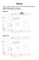
Notice There is a different between the PM915-478 & PM915P-478 Mainboard. PM915-478 Mainboard is w/ VGA port. PM915P-478 Mainboard is w/o VGA port.
PM915-478 Mainboard User’s Manual Rev:EG 1.1 Date:2009.
CONTENTS CHAPTER 1 INTRODUCTION............................ 2 1.1 1.2 1.3 Chipset Introduction ...................................... 2 Specification ............................................. 2 Mainboard Introduction .................................... 2 CHAPTER 2 PACKAGE CONTENTS........................ 3 CHAPTER 3 MAINBOARD LOCATIONS..................... 4 CHAPTER 4 INSTALLATION............................ 5 4.1 Jumper Setting and Slot ................................... 5 CHAPTER 5 BIOS SETUP..
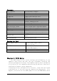
Chapter 1 Introduction 1.1 Chipset Introduction Intel 915GL Chipset The Intel 915GL chipset supports the latest PC technologies such as Socket 478 CPU, dual-channel DDR memory architecture and AGPe graphics card interface. Intel Graphics Media Accelerator 900 provides a significant increase in graphics performance.8 high-speed USB 2.0 ports. Dual-channel DDR This Intel 915GL chipset motherboard support TWO DDR DIMM interface that can make you have more use room.
-Built-in Powerful Integrated Graphics Integrated display function technologies without extend VGA card Integrated 2D/3D Graphics Controller -Provides one channel connecting two IDE drives Supports Ultra ATA66/100 synchronous DMA modes -Provides four channel connecting four SATA drives With speed up to 150MB/s -I/O : One floppy port support format 360K/720K/1.2M/1.44M/2.88M disk driver One serial port One parallel port,supports EPP/ECP/SPP transfers Eight USB2.
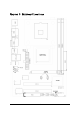
Chapter 3 Mainboard Locations 4
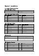
Chapter 4 Installation 4.1 Jumper Setting and Slot Clear CMOS Jumper setting 1-2(Default) 2-3 Normal Clear CMOS Audio:Front panel Jumper setting PIN Function PIN 1 MIC+ 2 3 Vbias 4 5 AuD_R_Out 6 7 N.C.
Connectors PS/2(Bottom) PS/2(Top) R_USB1 F_USB2/LAN F_USB3 F_USB4 LPT COM1 VGA LINE OUT/LINE IN/MIC SPDIF_I/ SPDIF_O IDE SATA1/SATA3 FDD ATX/ATX_12V CPU_FAN/PWR_FAN Function Port Panel Power Supply LED HDD LED Power Supply Switch Reset Switch PS/2 Keyboard (Purple) PS/2 Mouse Header(Green) USB1/2 Connector Port USB3/4/LAN Connector Port USB5/6 Connector Port USB7/8 Connector Port Printer Connector Port Serial Port COM1 Connector Port On-board VGA connector Audio Output/Audio Input/Microphone Digital Input/
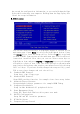
has stored the configuration information; or you can hold down the Page Up key while rebooting your computer. Holding down the Page Up key also clears the setup information 5.1 Main menu You can use cursor arrow keys to highlight anyone of options on the main menu page. Press Enter to select the highlighted option. Press the Escape key to leave the setup utility. Press the F9 key to go back to menu in BIOS.
Load Fail-Safe Defaults Setup the default values in system Load Optimized Defaults Setup the best performance values in system Set Supervisor Password Setup supervisor password in system Set User Password Setup user password in system Save & Exit Setup Setup save and exit, press Y to save and exit Exit Without Save Setup Setup without save and exit, press N to without save and exit 5.
Base Memory Expanded Memory Total Memory 5.
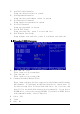
If you enable this item, the system will also search for other boot devices if it fails to find an operating system from the first two locations. Swap Floppy Drive Default:Disabled If you have two diskette drives installed and you enable this item, drive A becomes drive B and drive B becomes drive A.
Video BIOS Cacheable Memory Hole At 15M-16M PCI Express Root port Function PCI Express port 1 PCI Express port 2 PCI Express port 3 PCI Express port 4 PCI Express port 5 PCI Express port 6 PCI-E Compliancy Mose **VGA Setting ** PEG/Onchip VGA Control On-chip Frame Buffer Size DVMT Mode FIXED Memory Size DVMT Memory Size Boot Display Default:Disabled Default:Disabled Default: Press Enter Default: Auto Default: Auto Default: Auto Default: Auto Default: Auto Default: Auto Default: v1.
*** On-Chip Serial ATA Setting *** X SATA Mode On-chip serial ATA X SATA PORT Speed Settings PATA IDE Mode SATA Port Onboard Device USB Controller USB 2.
POWER ON Function X KB Power ON Password X Hot Key Power ON Onboard FDC Controller Setup onboard FDC controller Onboard Serial Port 1/2 Setup onboard serial port1/2 UART Mode Select Setup UART mode select UR2 Duplex Mode Onboard Parallel Port Setup select parallel port Parallel Port Mode Setup parallel port mode ECP Mode USE DMA PWRON After PWR-Fail Default: BUTTON ONLY Default: Enter Default: Ctrl-F1 Default: Enabled Default:3F8/IRQ4/2F8/IRQ4 Default:Normal Default:Half Default:378/IRQ
Wake-up by PCI card Default:Disabled Power On by Ring Resume by Alarm Date (of Month) Alarm Time (hh:mm:ss) Alarm ** Reload Global Timer Events ** Default: Disabled Default:Disabled Default:0 Default:0 Primary/ Secondary IDE 0/1 Default:Disabled FDD,COM,LPT Port Default:Disabled PCI PIRQ [A-D]# Default: Disabled 5.7 Set Supervisor Password &Set User Password If you highlight this item and press Enter, a dialog box appears that you can enter a supervisor password.