
Intel Pentium M Processor with 2-MB L2 Cache and 533-MHz Front Side Bus Datasheet

Datasheet 33
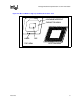
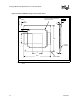
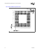
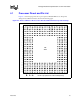
Package Mechanical Specifications and Pin Information
NOTES:
1. Overall height as delivered. Values are based on design specifications and tolerances. This dimension is
subject to change based on OEM motherboard design or OEM SMT process.
2. All dimensions are preliminary and subject to change.
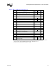
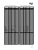
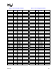
Table 4-2. Micro-FCBGA Package Dimensions
Symbol Parameter Min Max Unit
A Overall height, as delivered (Refer to Note 1) 2.60 2.85 mm
A2 Die height 0.82 mm
b Ball diameter 0.78 mm
D Package substrate length 34.9 35.1 mm
E Package substrate width 34.9 35.1 mm
D1 Die length 12.54 mm
E1 Die width 6.99 mm
e Ball pitch 1.27 mm
K Package edge keep-out 5 mm
K1 Package corner keep-out 7 mm
K2 Die-side capacitor height - 0.7 mm
S Package edge to first ball center 1.625 mm
N Ball count 479 each
- Solder ball coplanarity 0.2 mm
Pdie Allowable pressure on the die for thermal solution - 689 kPa
W Package weight 4.5 g