
Intel Pentium M Processor with 2-MB L2 Cache and 533-MHz Front Side Bus Datasheet


Datasheet 61
Thermal Specifications and Design Considerations
5.1 Thermal Specifications
5.1.1 Thermal Diode
The Pentium M Processor incorporates two methods of monitoring die temperature, the Intel
®
Thermal Monitor and the thermal diode. The Intel Thermal Monitor (detailed in Section 5.1) must
be used to determine when the maximum specified processor junction temperature has been
reached. The second method, the thermal diode, can be read by an off-die analog/digital converter
(a thermal sensor) located on the motherboard, or a stand-alone measurement kit. The thermal
diode may be used to monitor the die temperature of the processor for thermal management or
instrumentation purposes but cannot be used to indicate that the maximum T
J
of the processor has
been reached. When using the thermal diode, a temperature offset value must be read from a
processor Model Specific Register (MSR) and applied. See Section 6.1.2 for more details. Please
see Section 5.1.3 for thermal diode usage recommendation when the PROCHOT# signal is not
asserted.
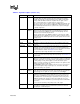
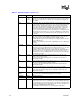
Table 5-2 and Table 5-3 provide the diode interface and specifications.
Note: The reading of the external thermal sensor (on the motherboard) connected to the processor
thermal diode signals, will not necessarily reflect the temperature of the hottest location on the die.
This is due to inaccuracies in the external thermal sensor, on-die temperature gradients between the
location of the thermal diode and the hottest location on the die, and time based variations in the die
temperature measurement. Time based variations can occur when the sampling rate of the thermal
diode (by the thermal sensor) is slower than the rate at which the T
J
temperature can change.
Offset between the thermal diode based temperature reading and the Intel Thermal Monitor reading
may be characterized using the Intel Thermal Monitor’s Automatic mode activation of thermal
control circuit. This temperature offset must be taken into account when using the processor
thermal diode to implement power management events.
5.1.2 Thermal Diode Offset
A temperature offset value (specified as Toffset in Table 5-3) will be programmed into a the
Pentium M Processor Model Specific Register (MSR). This offset is determined by using a thermal
diode ideality factor mean value of n = 1.0022 (shown in Table 5-3) as a reference. This offset must
be applied to the junction temperature read by the thermal diode. Any temperature adjustments due
to differences between the reference ideality value of 1.0022 and the default ideality values
programmed into the on-board thermal sensors, will have to be made before the above offset is
applied.
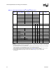
Table 5-2. Thermal Diode Interface
Signal Name Pin/Ball Number Signal Description
THERMDA B18 Thermal diode anode
THERMDC A18 Thermal diode cathode