
Datasheet

Functional Description
R
Datasheet 199
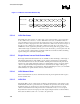
The digital display port consists of a digital data bus, VSYNC, HSYNC, and BLANK# signals.
The data bus can operate in a 12-bit or 24-bit mode. Embedded sync information or HSYNC and
VSYNC signals can optionally provide the basic timing information to the external device and the
BLANK# signal indicates which clock cycles contain valid data. The BLANK# signal can be
optionally selected to include the border area of the timing. The VSYNC and HSYNC signals can
be disabled when embedded sync information is to be used or to support DPMS. SYNC polarity
can be adjusted using the VGA polarity selection bits or the port configuration bits. Optionally a
STALL signal can cause the next line of data to not be sent until the STALL signal is removed.
Optionally the FIELD pin can indicate to the overlay which field is currently being displayed at
the display device.
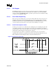
5.6 AGP Interface Overview
The GMCH/MCH supports 1.5 V AGP 1X/2X/4X devices. The AGP signal buffers are 1.5 V
drive/receive (buffers are not 3.3 Volt tolerant). The GMCH/MCH supports 2X/4X source
synchronous clocking transfers for read and write data, and sideband addressing. The
GMCH/MCH also supports 2X and 4X clocking for Fast Writes initiated from the GMCH/MCH
(on behalf of the processor).
AGP PIPE# or SBA[7:0] transactions to DRAM do not get snooped and are, therefore, not
coherent with the processor caches. AGP FRAME# transactions to DRAM are snooped. AGP
PIPE# and SBA[7:0] accesses to and from the hub interface are not supported. AGP FRAME#
access from an AGP master to the hub interface is also not supported. Only the AGP FRAME
memory writes from the hub interface are supported.
5.6.1 AGP Target Operations
As an initiator, the GMCH does not initiate cycles using AGP enhanced protocols. The
GMCH/MCH supports AGP cycles targeting interface to main memory only. The GMCH
supports interleaved AGP PIPE#] and AGP FRAME#, or AGP SBA[7:0] and AGP FRAME#
transactions.
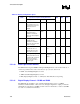
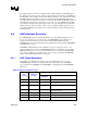
Table 44. Display Configuration Space
GMCH/MCH Host Bridge Max
AGP
Command
C/BE[3:0]#
Encoding
Cycle
Destination
Response as PCIx Target
Read 0000 Main Memory Low Priority Read
0000 The hub interface Complete locally with random data; does not
go to the hub interface
Hi-Priority
Read
0001 Main Memory High Priority Read
0000 The hub interface Complete locally with random data; does not
go to the hub interface
Reserved 0010 N/A No Response
Reserved 0011 N/A No Response
Write 0100 Main Memory Low Priority Write