
Intel 64 and IA-32 Architectures Software Developers Manual Volume 2B, Instruction Set Reference, N-Z


Vol. 2B A-5
OPCODE MAP
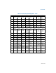
Example A-1. Look-up Example for 1-Byte Opcodes
Opcode 030500000000H for an ADD instruction is interpreted using the 1-byte
opcode map (Table A-2) as follows:
• The first digit (0) of the opcode indicates the table row and the second digit (3)
indicates the table column. This locates an opcode for ADD with two operands.
• The first operand (type Gv) indicates a general register that is a word or
doubleword depending on the operand-size attribute. The second operand (type
Ev) indicates a ModR/M byte follows that specifies whether the operand is a word
or doubleword general-purpose register or a memory address.
• The ModR/M byte for this instruction is 05H, indicating that a 32-bit displacement
follows (00000000H). The reg/opcode portion of the ModR/M byte (bits 3-5) is
000, indicating the EAX register.
The instruction for this opcode is ADD EAX, mem_op, and the offset of mem_op is
00000000H.
Some 1- and 2-byte opcodes point to group numbers (shaded entries in the opcode
map table). Group numbers indicate that the instruction uses the reg/opcode bits in
the ModR/M byte as an opcode extension (refer to Section A.4).
A.2.4.2 Two-Byte Opcode Instructions
The two-byte opcode map shown in Table A-3 includes primary opcodes that are
either two bytes or three bytes in length. Primary opcodes that are 2 bytes in length
begin with an escape opcode 0FH. The upper and lower four bits of the second
opcode byte are used to index a particular row and column in Table A-3.
Two-byte opcodes that are 3 bytes in length begin with a mandatory prefix (66H,
F2H, or F3H) and the escape opcode (OFH). The upper and lower four bits of the third
byte are used to index a particular row and column in Table A-3 (except when the
second opcode byte is the 3-byte escape opcodes 38H or 3AH; in this situation refer
to Section A.2.4.3).
For each entry in the opcode map, the rules for interpreting the byte following the
primary opcode fall into one of the following cases:
• A ModR/M byte is required and is interpreted according to the abbreviations listed
in Section A.1 and Chapter 2, “Instruction Format,” of the Intel® 64 and IA-32
Architectures Software Developer’s Manual, Volume 2A. The operand types are
listed according to notations listed in Section A.2.
• A ModR/M byte is required and includes an opcode extension in the reg field in
the ModR/M byte. Use Table A-6 when interpreting the ModR/M byte.
• Use of the ModR/M byte is reserved or undefined. This applies to entries that
represent an instruction without operands that are encoded using ModR/M (for
example: 0F77H, EMMS).