
Intel 64 and IA-32 Architectures Software Developers Manual Volume 2B, Instruction Set Reference, N-Z

A-22 Vol. 2B
OPCODE MAP
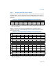
A.5 ESCAPE OPCODE INSTRUCTIONS
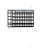
Opcode maps for coprocessor escape instruction opcodes (x87 floating-point
instruction opcodes) are in Table A-7 through Table A-22. These maps are grouped
by the first byte of the opcode, from D8-DF. Each of these opcodes has a ModR/M
byte. If the ModR/M byte is within the range of 00H-BFH, bits 3-5 of the ModR/M byte
are used as an opcode extension, similar to the technique used for 1-and 2-byte
opcodes (see Section A.4). If the ModR/M byte is outside the range of 00H through
BFH, the entire ModR/M byte is used as an opcode extension.
A.5.1 Opcode Look-up Examples for Escape Instruction Opcodes
Examples are provided below.
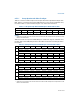
Example A-5. Opcode with ModR/M Byte in the 00H through BFH Range
DD0504000000H can be interpreted as follows:
• Since the ModR/M byte (05H) is within the 00H through BFH range, bits 3 through
5 (000) of this byte indicate the opcode for an FLD double-real instruction (see
Table A-9).
• The double-real value to be loaded is at 00000004H (the 32-bit displacement
that follows and belongs to this opcode).
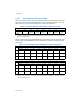
Example A-3. Opcode with ModR/M Byte outside the 00H through BFH Range
D8C1H can be interpreted as follows:
• This example illustrates an opcode with a ModR/M byte outside the range of 00H
through BFH. The instruction can be located in Section A.4.
• In Table A-8, the ModR/M byte C1H indicates row C, column 1 (the FADD
instruction using ST(0), ST(1) as operands).
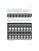
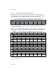
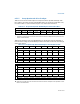
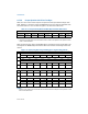
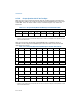
A.5.2 Escape Opcode Instruction Tables
Tables are listed below.