
Intel 64 and IA-32 Architectures Software Developers Manual Volume 2B, Instruction Set Reference, N-Z


Vol. 2B A-1
APPENDIX A
OPCODE MAP
Use the opcode tables in this chapter to interpret Intel 64 and IA-32 architecture
object code. Instructions are divided into encoding groups:
• 1-byte, 2-byte and 3-byte opcode encodings are used to encode integer, system,
MMX technology, SSE/SSE2/SSE3/SSSE3, and VMX instructions. Maps for these
instructions are given in Table A-2 through Table A-6.
• Escape opcodes (in the format: ESC character, opcode, ModR/M byte) are used
for floating-point instructions. The maps for these instructions are provided in
Table A-7 through Table A-22.
NOTE
All blanks in opcode maps are reserved and must not be used. Do not
depend on the operation of undefined or blank opcodes.
A.1 USING OPCODE TABLES
Tables in this appendix list opcodes of instructions (including required instruction
prefixes, opcode extensions in associated ModR/M byte). Blank cells in the tables
indicate opcodes that are reserved or undefined.
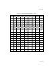
The opcode map tables are organized by hex values of the upper and lower 4 bits of
an opcode byte. For 1-byte encodings (Table A-2), use the four high-order bits of an
opcode to index a row of the opcode table; use the four low-order bits to index a
column of the table. For 2-byte opcodes beginning with 0FH (Table A-3), skip any
instruction prefixes, the 0FH byte (0FH may be preceded by 66H, F2H, or F3H) and
use the upper and lower 4-bit values of the next opcode byte to index table rows and
columns. Similarly, for 3-byte opcodes beginning with 0F38H or 0F3AH (Table A-4),
skip any instruction prefixes, 0F38H or 0F3AH and use the upper and lower 4-bit
values of the third opcode byte to index table rows and columns. See Section A.2.4,
“Opcode Look-up Examples for One, Two, and Three-Byte Opcodes.”
When a ModR/M byte provides opcode extensions, this information qualifies opcode
execution. For information on how an opcode extension in the ModR/M byte modifies
the opcode map in Table A-2 and Table A-3, see Section A.4.
The escape (ESC) opcode tables for floating point instructions identify the eight high
order bits of opcodes at the top of each page. See Section A.5. If the accompanying
ModR/M byte is in the range of 00H-BFH, bits 3-5 (the top row of the third table on
each page) along with the reg bits of ModR/M determine the opcode. ModR/M bytes
outside the range of 00H-BFH are mapped by the bottom two tables on each page of
the section.