
Intel 64 and IA-32 Architectures Software Developers Manual Volume 2B, Instruction Set Reference, N-Z

B-96 Vol. 2B
INSTRUCTION FORMATS AND ENCODINGS
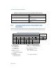
B.12 FLOATING-POINT INSTRUCTION FORMATS AND
ENCODINGS
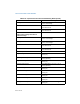
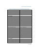
Table B-33 shows the five different formats used for floating-point instructions. In all
cases, instructions are at least two bytes long and begin with the bit pattern 11011.
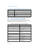
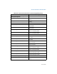
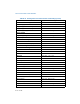
mmreg to reg64 0100 1R0B 0000 1111:1101 0111:11 r64
mmreg
xmmreg to reg32 0100 0RXB 0110 0110 0000 1111:1101
0111:11 r32 mmreg
xmmreg to reg64 0110 0110 0000 1111:1101 0111:11 r64
xmmreg
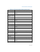
Table B-33. General Floating-Point Instruction Formats
Instruction
First Byte Second Byte
Optional Fields
1 11011 OPA 1 mod 1 OPB r/m s-i-b disp
2 11011 MF OPA mod OPB r/m s-i-b disp
3 11011 d P OPA 1 1 OPB R ST(i)
4 11011 0 0 1 1 1 1 OP
5 11011 0 1 1 1 1 1 OP
15–11 10 9 8 7 6 5 4 3 2 1 0
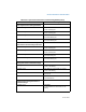
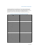
MF = Memory Format
00 — 32-bit real
01 — 32-bit integer
10 — 64-bit real
11 — 16-bit integer
P = Pop
0 — Do not pop stack
1 — Pop stack after operation
d = Destination
0 — Destination is ST(0)
1 — Destination is ST(i)
R XOR d = 0 — Destination OP Source
R XOR d = 1 — Source OP Destination
ST(i) = Register stack element i
000 = Stack Top
001 = Second stack element
⋅
⋅
⋅
111 = Eighth stack element
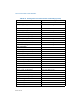
Table B-32. Special Case Instructions Promoted Using REX.W (Contd.)
Instruction and Format Encoding