
Technical Product Specification


Intel® Server Board S1200V3RP TPS On-board Connector/Header Overview
Revision 1.3
85
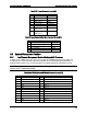
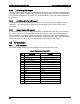
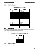
Table 48. Internal USB3.0 Connector Pin-out (J1J1)
Pin
Signal
Description
1
Vbus
Power
2
IntA_P1_SSRX-
USB3 ICC Port1 SuperSpeed Rx-
3
IntA_P1_SSRX+
USB3 ICC Port1 SuperSpeed Rx+
4
GND
Ground
5
IntA_P1_SSTX-
USB3 ICC Port1 SuperSpeed Tx-
6
IntA_P1_SSTX+
USB3 ICC Port1 SuperSpeed Tx+
7
GND
Ground
8
IntA_P1_D-
USB3 ICC Port1 D- (USB2 Signal D-)
9
IntA_P1_D+
USB3 ICC Port1 D+ (USB2 Signal D+)
10
ID
Over Current Protection
11
IntA_P2_D+
USB3 ICC Port2 D+ (USB2 Signal D+)
12
IntA_P2_D-
USB3 ICC Port2 D- (USB2 Signal D-)
13
GND
Ground
14
IntA_P2_SSTX+
USB3 ICC Port2 SuperSpeed Tx+
15
IntA_P2_SSTX-
USB3 ICC Port2 Super Speed Tx-
16
GND
Ground
17
IntA_P2_SSRX+
USB3 ICC Port2 SuperSpeed Rx+
18
IntA_P2_SSRX-
USB3 ICC Port2 SuperSpeed Rx-
19
Vbus
Power
20
KEY PIN
No pin
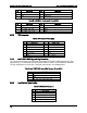
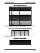
The server board includes one 10-pin 2mm low-profile connector (J5K1) on the server boards
provides an option to support a low-profile eUSB Solid State Drive.
Table 49. Pin-out of Internal Low-Profile USB Connector (eUSB) for Solid State Drive (J5K1)
Pin
Signal
Pin
Signal
1
+5V
6
NC
2
USB_N
7
NC
3
USB_P
8
NC
4
GND
9
NC
5
Key Pin
10
LED#
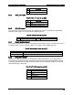
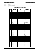
The server board provides one additional Type A USB port (J1J4) to support the installation of a
USB device inside the server chassis.
Table 50. Internal Type A USB Port Pin-out (J1J4)
Pin
Signal Name
Description
1
USB_PWR7_5V
USB_PWR
2
USB_PN
USB port negative signal
3
USB _PP
USB port positive signal
4
GND
Ground