Intel® Server System R1000RP Family Quick Installation User's Guide Thank you for buying an Intel® Server System. The following information will help you assemble your Intel® Server System and install components. If you are not familiar with ESD [ElectroStatic Discharge] procedures used during system integration, see the complete ESD procedures described in your Service Guide. This guide and other supporting documents are located on the web at: http://www.intel.com/p/en_US/support/. * 2.
(This page is intentionally left blank.
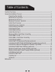
Table of Contents System Overview .............................................................................................................................. 1 General Installation Process ........................................................................................................ 2 Preparing the System ...................................................................................................... 2 Remove the Top Cover ..................................................................
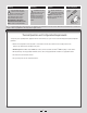
Warning Read all caution and safety statements in this document before performing any of the instructions. Also see the Intel ® Server Board and Server Chassis Safety Information document at: http://www.intel.com/support/ motherboards/server/sb/cs-010770 .htm for complete safety information. Warning Caution Installation and service of this product is to be performed only by qualified service personnel to avoid risk of injury from electrical shock or energy hazard.
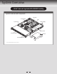
System Overview Intel® Server System R1000RP Family System Features and Components PCI Slots Server Board CPU Power Supply System Fans Memory Slots Hard Drive Bays Air Duct Front Control Panel * 2.
General Installation Process The installation instructions in this section are for common components of Intel® Server System R1000RP family. 1 Minimum Hardware Requirements To avoid integration difficulties and possible board damage, your system must meet the following minimum requirements: Observe normal ESD (Electrostatic Discharge) procedures. • Processor: Intel® Xeon® processor E3-1200 V3 product family or the 4th Generation Intel® Core™ i3 processor series.
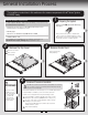
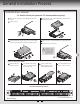
General Installation Process 5 Install the Processor A. Open the Socket Lever Cautions: A When removing the protective cover, DO NOT TOUCH the gold socket pins. B To avoid damage, DO NOT DROP the cover onto the socket pins or components. C When unpacking a processor, hold by the edges only to avoid touching the gold contact pins. A Push the lever handle down and away from the socket to release it. B B. Open the Load Plate A Open the load plate as shown. Rotate the lever open all the way. C.
General Installation Process 6 7 Install Processor Heatsink CAUTION: Do not over-tighten fasteners. CAUTION: The heatsink has thermal interface material (TIM) on the underside of it. Use caution so that you do not damage the thermal interface material. Use gloves to avoid sharp edges. A Remove the protective film on the TIM if present. B Align heatsink fins to the front and back of the chassis for correct airflow. Airflow goes from front-to-back of chassis.
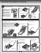
General Installation Process 8 Install Hard Drives 2.5" Hard Drive Carrier (For system with 2.5" hard drive bay only) A Remove the drive carrier by pressing the green latch to unlock. B Pull out the black lever and slide the carrier out. E Install the hard disk drive using the four screws as shown. Make Sure that the connector end of the drive matches the backplane connector. 5" 2. D HD A E B C Remove the four screws securing the plastic drive blank from the 2.5” HDD carrier.
General Installation Process Install Hard Drives ...continued 3.5" Hard Drive Carrier (For system with 3.5" Hot Swap hard drive bay only) Remove the drive carrier by pressing the green button and opening the lever. B Slide the carrier out. TO P C Remove the four screws securing the HDD interface bracket and remove the HDD interface bracket. TO P BRE 2.5´´BEFOR AK OF HAR E MO F TAB D D UTIN RIV G E B AB NG F T TI E OF OU IV K M DR EA RE RD BR EFO HA B 5´´ 2.
General Installation Process Install Hard Drives ...continued 3.5" Fixed Hard Drive B A Remove the screws securing the drive carrier to the chassis. B Slide the carrier away from the chassis. C Screw A Insert hard drive into the carrier with the bottom-side of the drive facing up. C Note: Hard drive 0 location is shown above. D Attach the hard drive to the carrier with four screws as shown. E D Re-install the hard drive/carrier assembly into the chassis.
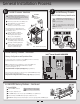
General Installation Process 10 11 Install the Air Duct Align the two holes on the air duct with the alignment pins on the chassis and install the air duct into place. Use care to avoid pinching system cables. Remove Add-in Card Riser Assembly CAUTION: Place the riser assembly upside down to avoid damage to the riser card connector. Grasp the riser assembly with both hands and pull up to remove from system.
General Installation Process 15 16 Install Intel® I/O Expansion Module (optional) Install Intel® ESRT2 RAID AXXRAKSW5 Upgrade Key (optional) D A B Squeeze the sides of the filler panel to disengage it from the server system back panel and remove it. I/O D Secure the module with the three screws as shown. A B C EY _K TA Attach the module to the server board connector. Locate the white 4-pin key, carefully pick up the Intel® RAID C600 Upgrade Key.
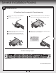
General Installation Process 18 Install Intel® RAID Smart Battery (optional) A Locate the BBU bracket inside the chassis. Align the tabs on the plastic battery holder with mounting holes on the BBU bracket. B Slide the plastic battery holder toward the rear of the system until the tabs engage with the mounting holes in the BBU bracket. A B 19 Replace Fixed Power Supply Module (optional) A A B B 20 A Unsecure the three screws from the module as shown.
General Installation Process 21 22 Install Bezel (optional) Note: Before installing the bezel, you must install the rack handles. A B A Lock the right end of the front bezel to the rack handle. Install the Top Cover Place the top cover on system and slide towards the front of the chassis until the recessed front edge is fully engaged. Rotate the front bezel clockwise till the left end clicks into place. Lock the bezel if needed.
Reference Front Panel Controls and Indicators Standard Control Panel G Your system may include one of two front control panel types. The features of each are as follows: A. ID Button with integrated LED B. NMI Button C. LAN-1 Activity LED D. System Cold Reset Button H E. System Status LED F. Power Button with integrated LED G. LAN-2 Activity LED H.
Reference System Fan Connection FAN 1 FAN 2 DIMM_B1 DIMM_B2 DIMM_A1 DIMM_A2 FAN 4 FAN 3 Fixed System Fans Air F 1 2 3 A complete list of accessories and spares can be found at: http://www.intel.com/p/en_US/support/ (post-production only).
Reference System Cabling Diagram For system with 4 x 3.5” fixed hard drive bay: Intel® Integrated RAID Module CPU Power Front Panel USB Front Panel PS AUX SATA 4 SATA 3 SATA 1 SATA 2 SATA 0 Main Power SAS Module SYS FAN_1 BBU 7 Pin SATA SYS FAN_2 SYS FAN_3 FAN 1 1x5 Pin SATA Pwr 3.5” SATA HDD 7 Pin SATA FAN 2 1x5 Pin SATA Pwr 3.5” SATA HDD 7 Pin SATA 1x5 Pin SATA Pwr 3.5” SATA HDD 7 Pin SATA FAN 3 1x5 Pin SATA Pwr 3.
Reference System Cabling Diagram For system with 4 x 3.5” hot swap hard drive bay: Intel® Integrated RAID Module CPU Power Front Panel USB Front Panel PS AUX 350W Power Supply SATA 4 SATA 3 SATA 1 SATA 2 SATA 0 HSBP_I2C Main Power SAS Module SYS FAN_1 SYS FAN_2 SYS FAN_3 I2C BBU HDD O FAN 1 SATA SGPIO FAN 2 4 x 3.
Reference System Cabling Diagram For system with 8 x 2.5” hot swap hard drive bay: Intel® Integrated RAID Module CPU Power Front Panel PS AUX 450W Power Supply Front Panel USB PDB HSBP_I2C Main Power SAS Module SYS FAN_1 SYS FAN_2 SYS FAN_3 SATA 0 BBU I2C FAN 1 FAN 2 FAN 3 8 x 2.
G85599-002
Intel® Server System R1000RP Family Quick Installation User's Guide Thank you for buying an Intel® Server System. The following information will help you assemble your Intel® Server System and install components. If you are not familiar with ESD [ElectroStatic Discharge] procedures used during system integration, see the complete ESD procedures described in your Service Guide. This guide and other supporting documents are located on the web at: http://www.intel.com/p/en_US/support/. * 2.
(This page is intentionally left blank.
Table of Contents System Overview .............................................................................................................................. 1 General Installation Process ........................................................................................................ 2 Preparing the System ...................................................................................................... 2 Remove the Top Cover ..................................................................
Warning Read all caution and safety statements in this document before performing any of the instructions. Also see the Intel ® Server Board and Server Chassis Safety Information document at: http://www.intel.com/support/ motherboards/server/sb/cs-010770 .htm for complete safety information. Warning Caution Installation and service of this product is to be performed only by qualified service personnel to avoid risk of injury from electrical shock or energy hazard.
System Overview Intel® Server System R1000RP Family System Features and Components PCI Slots Server Board CPU Power Supply System Fans Memory Slots Hard Drive Bays Air Duct Front Control Panel * 2.
General Installation Process The installation instructions in this section are for common components of Intel® Server System R1000RP family. 1 Minimum Hardware Requirements To avoid integration difficulties and possible board damage, your system must meet the following minimum requirements: Observe normal ESD (Electrostatic Discharge) procedures. • Processor: Intel® Xeon® processor E3-1200 V3 product family or the 4th Generation Intel® Core™ i3 processor series.
General Installation Process 5 Install the Processor A. Open the Socket Lever Cautions: A When removing the protective cover, DO NOT TOUCH the gold socket pins. B To avoid damage, DO NOT DROP the cover onto the socket pins or components. C When unpacking a processor, hold by the edges only to avoid touching the gold contact pins. A Push the lever handle down and away from the socket to release it. B B. Open the Load Plate A Open the load plate as shown. Rotate the lever open all the way. C.
General Installation Process 6 7 Install Processor Heatsink CAUTION: Do not over-tighten fasteners. CAUTION: The heatsink has thermal interface material (TIM) on the underside of it. Use caution so that you do not damage the thermal interface material. Use gloves to avoid sharp edges. A Remove the protective film on the TIM if present. B Align heatsink fins to the front and back of the chassis for correct airflow. Airflow goes from front-to-back of chassis.
General Installation Process 8 Install Hard Drives 2.5" Hard Drive Carrier (For system with 2.5" hard drive bay only) A Remove the drive carrier by pressing the green latch to unlock. B Pull out the black lever and slide the carrier out. E Install the hard disk drive using the four screws as shown. Make Sure that the connector end of the drive matches the backplane connector. 5" 2. D HD A E B C Remove the four screws securing the plastic drive blank from the 2.5” HDD carrier.
General Installation Process Install Hard Drives ...continued 3.5" Hard Drive Carrier (For system with 3.5" Hot Swap hard drive bay only) Remove the drive carrier by pressing the green button and opening the lever. B Slide the carrier out. TO P C Remove the four screws securing the HDD interface bracket and remove the HDD interface bracket. TO P BRE 2.5´´BEFOR AK OF HAR E MO F TAB D D UTIN RIV G E B AB NG F T TI E OF OU IV K M DR EA RE RD BR EFO HA B 5´´ 2.
General Installation Process Install Hard Drives ...continued 3.5" Fixed Hard Drive B A Remove the screws securing the drive carrier to the chassis. B Slide the carrier away from the chassis. C Screw A Insert hard drive into the carrier with the bottom-side of the drive facing up. C Note: Hard drive 0 location is shown above. D Attach the hard drive to the carrier with four screws as shown. E D Re-install the hard drive/carrier assembly into the chassis.
General Installation Process 10 11 Install the Air Duct Align the two holes on the air duct with the alignment pins on the chassis and install the air duct into place. Use care to avoid pinching system cables. Remove Add-in Card Riser Assembly CAUTION: Place the riser assembly upside down to avoid damage to the riser card connector. Grasp the riser assembly with both hands and pull up to remove from system.
General Installation Process 15 16 Install Intel® I/O Expansion Module (optional) Install Intel® ESRT2 RAID AXXRAKSW5 Upgrade Key (optional) D A B Squeeze the sides of the filler panel to disengage it from the server system back panel and remove it. I/O D Secure the module with the three screws as shown. A B C EY _K TA Attach the module to the server board connector. Locate the white 4-pin key, carefully pick up the Intel® RAID C600 Upgrade Key.
General Installation Process 18 Install Intel® RAID Smart Battery (optional) A Locate the BBU bracket inside the chassis. Align the tabs on the plastic battery holder with mounting holes on the BBU bracket. B Slide the plastic battery holder toward the rear of the system until the tabs engage with the mounting holes in the BBU bracket. A B 19 Replace Fixed Power Supply Module (optional) A A B B 20 A Unsecure the three screws from the module as shown.
General Installation Process 21 22 Install Bezel (optional) Note: Before installing the bezel, you must install the rack handles. A B A Lock the right end of the front bezel to the rack handle. Install the Top Cover Place the top cover on system and slide towards the front of the chassis until the recessed front edge is fully engaged. Rotate the front bezel clockwise till the left end clicks into place. Lock the bezel if needed.
Reference Front Panel Controls and Indicators Standard Control Panel G Your system may include one of two front control panel types. The features of each are as follows: A. ID Button with integrated LED B. NMI Button C. LAN-1 Activity LED D. System Cold Reset Button H E. System Status LED F. Power Button with integrated LED G. LAN-2 Activity LED H.
Reference System Fan Connection FAN 1 FAN 2 DIMM_B1 DIMM_B2 DIMM_A1 DIMM_A2 FAN 4 FAN 3 Fixed System Fans Air F 1 2 3 A complete list of accessories and spares can be found at: http://www.intel.com/p/en_US/support/ (post-production only).
Reference System Cabling Diagram For system with 4 x 3.5” fixed hard drive bay: Intel® Integrated RAID Module CPU Power Front Panel USB Front Panel PS AUX SATA 4 SATA 3 SATA 1 SATA 2 SATA 0 Main Power SAS Module SYS FAN_1 BBU 7 Pin SATA SYS FAN_2 SYS FAN_3 FAN 1 1x5 Pin SATA Pwr 3.5” SATA HDD 7 Pin SATA FAN 2 1x5 Pin SATA Pwr 3.5” SATA HDD 7 Pin SATA 1x5 Pin SATA Pwr 3.5” SATA HDD 7 Pin SATA FAN 3 1x5 Pin SATA Pwr 3.
Reference System Cabling Diagram For system with 4 x 3.5” hot swap hard drive bay: Intel® Integrated RAID Module CPU Power Front Panel USB Front Panel PS AUX 350W Power Supply SATA 4 SATA 3 SATA 1 SATA 2 SATA 0 HSBP_I2C Main Power SAS Module SYS FAN_1 SYS FAN_2 SYS FAN_3 I2C BBU HDD O FAN 1 SATA SGPIO FAN 2 4 x 3.
Reference System Cabling Diagram For system with 8 x 2.5” hot swap hard drive bay: Intel® Integrated RAID Module CPU Power Front Panel PS AUX 450W Power Supply Front Panel USB PDB HSBP_I2C Main Power SAS Module SYS FAN_1 SYS FAN_2 SYS FAN_3 SATA 0 BBU I2C FAN 1 FAN 2 FAN 3 8 x 2.
G85599-002