
Technical Product Specification


Intel
®
Server System R1000RP Family TPS Appendix B: POST Code LED Decoder
Revision 1.3 Intel
order number: G91532-003 61
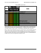
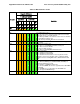
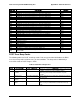
Table 32. MRC Progress Codes
Checkpoint
Diagnostic LED Decoder
Description
1 = LED On, 0 = LED Off
Upper Nibble
Lower Nibble
MSB
LSB
8h
4h
2h
1h
8h
4h
2h
1h
LED
#7
#6
#5
#4
#3
#2
#1
#0
MRC Progress Codes
B0h
1
0
1
1
0
0
0
0
Detect DIMM population
B1h
1
0
1
1
0
0
0
1
Set DDR3 frequency
B2h
1
0
1
1
0
0
1
0
Gather remaining SPD data
B3h
1
0
1
1
0
0
1
1
Program registers on the memory controller level
B4h
1
0
1
1
0
1
0
0
Evaluate RAS modes and save rank information
B5h
1
0
1
1
0
1
0
1
Program registers on the channel level
B6h
1
0
1
1
0
1
1
0
Perform the JEDEC defined initialization sequence
B7h
1
0
1
1
0
1
1
1
Train DDR3 ranks
B8h
1
0
1
1
1
0
0
0
Initialize CLTT/OLTT
B9h
1
0
1
1
1
0
0
1
Hardware memory test and init
BAh
1
0
1
1
1
0
1
0
Execute software memory init
BBh
1
0
1
1
1
0
1
1
Program memory map and interleaving
BCh
1
0
1
1
1
1
0
0
Program RAS configuration
BFh
1
0
1
1
1
1
1
1
MRC is done
Memory initialization at the beginning of POST includes multiple functions, including discovery,
channel training, validation that the DIMM population is acceptable and functional, initialization
of the IMC and other hardware settings, and initialization of applicable RAS configurations.
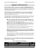
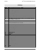
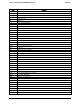
When a major memory initialization error occurs and prevents the system from booting with data
integrity, a beep code is generated, the MRC will display a fatal error code on the diagnostic
LEDs, and a system halt command is executed. Fatal MRC error halts do NOT change the state
of the System Status LED, and they do NOT get logged as SEL events. The following table lists
all MRC fatal errors that are displayed to the Diagnostic LEDs.