Intel® Server System P4000RP Family Quick Installation User's Guide Thank you for buying an Intel® Server System. The following information will help you assemble your Intel® Server System and install components. If you are not familiar with ESD [Electrostatic Discharge] procedures used during system integration, see the complete ESD procedures described in your Service Guide. This guide and other supporting documents are located on the web at: http://www.intel.com/p/en_US/support.
(This page is intentionally left blank.
Table of Contents System Overview .............................................................................................................................. 1 General Installation Process ........................................................................................................ 3 Preparing the System ....................................................................................................... 3 Remove the Side Cover ................................................................
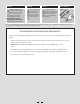
Warning Warning Caution Read all caution and safety statements in this document before performing any of the instructions. Also see the Intel ® Server Board and Server Chassis Safety Information document at: http://www.intel.com/support/ motherboards/server/sb/cs-010770 .htm for complete safety information. Installation and service of this product to be performed only by qualified service personnel to avoid risk of injury from electrical shock or energy hazard.
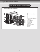
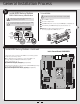
System Overview Intel® Server System P4308RPLSHDR System Features and Components A B C D J F K L G H M E N O I A B C D E F G H I J K L 460W Hot Swap Power Supply (Two) AC Input Power Connector (Two) I/O Ports RMM4 Knockout PCI Add-in Board Slot Covers Alternate Serial Port Knockout A Kensington* Cable Lock Mounting Hole Padlock Loop Alternate RMM4 Knockout Front Control Panel 5.25" Peripheral Bays Active Heatsink M 8 x 3.
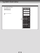
System Overview Hot Swap Hard Drive Bay Options and HDD Numbering A 8 x 3.
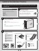
General Installation Process The installation instructions in this section are for general components of Intel® Server System P4000RP family. 1 Minimum Hardware Requirements To avoid integration difficulties and possible damage to your system, make sure you have components from each category below. ■ ■ ■ ■ ■ 2 Preparing the System Observe normal ESD (Electrostatic Discharge) procedures.
General Installation Process Install the Processor ... continued E. Close the Load Plate D. Install the Processor Carefully lower the load plate over the processor. CAUTION: The underside of the processor has components that may damage the socket wires if installed improperly. Carefully lower the load plate over the processor. Processor must align correctly with the socket opening Components before installation.
General Installation Process 5 Install DIMM Memory Modules To Install DIMMs: DDR3L DIMM Memory Identification: CAUTION: Avoid touching contacts when handling or installing DIMMs. CAUTION: Observe normal ESD (ElectroStatic Discharge) procedures to avoid possible damage to system components. A B C D E This server board supports up to 4 DDR3L 1333/1600 ECC UDIMM. Non-ECC memory is NOT supported by this server board. DIMM notch and socket bump must align as shown. Open both DIMM socket levers.
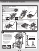
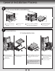
General Installation Process 6 Install Tool-less CD-ROM or DVD-ROM Drive Finger Holes B A 7 B Press the release latch and use the finger holes to Pull out the EMI shield. C D A Get the slides from the chassis side. C Attach slides to the DVD or CD-ROM drive by pressing the slides firmly into the side dimples on the DVD or CD-ROM drive. D Insert the drive/slide assembly into the device bay until the slides lock into place. Install Hard Drive 3.5" Hot-Swap Hard Drive Carrier TO P BRE 2.
General Installation Process 8 Install PCI-e Card Assembly A Remove the PCI slot shield by pushing the shield out from inside the chassis. B From inside of chassis, press open the back panel PCI add-in board retention device. C While holding the PCI add-in board by its top edge or upper corners, firmly press the add-in board into the expansion slot. D Close the PCI add-in board retention device.
General Installation Process 10 Install RMM4 EMI Cover (optional) A 11 Install Alternate Serial Port (optional) Chassis Back Opening Install the RMM4 EMI cover with thumb screws. A Filler D Seria Conn l B ector B C B A Remove the alternate serial port knockout by pressing the knockout from inside the chassis. CAUTION: Carefully remove the knock out with screwdriver, directly removing it with finger has potential risk. B C D Mount the serial serial port on the rear panel of the chassis.
General Installation Process 13 Install Second Power Supply Module (optional) Latch Finger Hole A A B B Use the 'finger hole' to remove the filler panel. Handle Insert the power supply module into the power supply cage and push all the way until it clicks into place. To remove a power supply module, push the green latch in the direction shown and pull out of the system by the handle. NOTE: Applies only to the chassis with hot-swap power supply configuration.
General Installation Process 16 Install Software • BIOS, Drivers, and Operating System Install A. Confirm BIOS Version: Look on the Server/System Management screen in the BIOS Setup Utility to determine the installed BIOS version. Compare this to the versions at: http://www.intel.com/support If new versions are available, update the BIOS on your server. See the User Guide on the Intel® Server Deployment and Management DVD for update instructions. B.
Reference HDD Cage Cable Connection NOTE: Refer to the documents which come with your server board and/or RAID controller card for instructions on connecting backplane cables to your server board or RAID controller card. 8 x 3.5" HDD Cage C B A A B C Connect the I2C cable to I2C connector on backplane. Connect Mini SAS data cables. Connect two power cables.
Reference Front Panel Controls and Indicators H A A USB Connectors B ID Button with ID LED Integrated C NMI Button B C D E F D NIC LED E System Reset Button F System Status LED G System Power Button with Power LED H HDD Activity LED Cable Routing Diagram Power Supply B C H A D E F CPU Power SYS_FAN_4 Main Power PS AUX K Intel® Integrated RAID Module Server Board I SYS_FAN_1 SAS SPGIO 2 HSBP_I C Front Panel USB J SATA G Intel® Server System P4304FP2SFCN Description A. B. C. D. E. F. G.
G85600-002