
Technical Advisory TA 1054


Copyright © 2014 Intel Corporation. * Other names and brands may be claimed as the property of others.
Corrective Action / Resolution
Intel has screened the current inventory to ensure systems and chassis are shipped with the correct SATA power
connectors.
Intel will provide the correct power cable to customers as a replacement upon request. Please contact Intel using your
normal warranty process to obtain the cable. Please indicate you are calling regarding TA-1054-01 for a replacement
cable with the part number DD0S6CPB700 and have the following information when you call: serial number(s) for the
system(s) or chassis.
The following is a brief instruction of how to replace the power cable that connects to the 2x12 pin connector (labeled
“Main PWR1”) on the PDB:
1. Remove the side cover and the air duct from the system or chassis by referring to the Service Guide of your
affected product. The Service Guide is available on http://www.intel.com/p/en_US/support
.
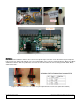
2. Remove wire tie and put it in a safe place for reuse.
Figure 4. Location of the wire tie
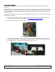
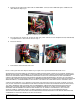
3. Note down the original locations of the P2, P3, P5, P6, P7, P8, P9, P10, P11 power connectors if they are
connected to the backplane board, motherboard, or peripheral devices, and then remove the connectors. See
the following figures for some location examples of these power connectors.
Figure 5. Location examples of the power connectors