
Technical Product Specification


Front Control Panel Intel® Server System R1304BTSSFAN/ R1304BTLSFAN/ R1304BTLSHBN TPS
7. Front Control Panel
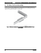
The standard control panel supports a power button, a status LED, a hard drive activity LED,
and NIC 1 and NIC 2 activity LEDs. The control panel assembly comes pre-assembled into the
chassis. The control panel assembly module slides into a predefined slot on the front of the
chassis. Once installed, communication to the server board is achieved through a standard
24-pin cable connected directly to the server board.
Note: The LAN3/4 LEDs are not used on the Intel
®
Server System R1304BTSSFAN,
R1304BTLSFAN, or R1304BTLSHBN. Unstuffable ID Button with ID LED and Status/Fault LED
are not used on the Intel
®
Server System R1304BTSSFAN.
A
Unstuffable ID Button with ID LED
F
Status/Fault LED
B
NMI Button
G
Power Button with power LED
C
LAN1 LED
H
LAN2 LED
D
LAN3 LED
I
LAN4 LED
E
Reset Button
J
HDD LED
Figure 16. Intel
®
Server System R1304BTSSFAN/R1304BTLSFAN/R1304BTLSHBN Front Control Panel
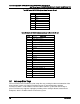
Table 27. Control Panel LED Functions
LED
Color
State
Description
NIC1/NIC2
Activity
Green
On
NIC Link/no access
Green
Blink
LAN access
Power/Sleep
(on standby power)
Green
On
Power on
Blink
Sleep/ACPI S1 state
Off
Off
Power Off/ACPI S4 state
Revision 2.4
28