
Technical Product Specification


Chassis Power Sub-system Intel
®
Server Chassis P4000S Family TPS
Intel order number G22850-006 Revision 1.5
64
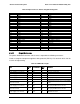
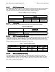
2.4.2.5 12V Rail Distribution
The following table shows the configuration of the 12V rails and what connectors and
components in the system they are powering.
Table 81. 12V Rail Distribution
P2
P3
P12
P1
P8
P9
P10
P11
P5,6,7
2x4
2x2
2x12
1x4
1x4
1x4
1x4
(2) 1x5,
1x4
OCP
CPU1
Memory1
CPU2
Memory2
PCIe
Fans
Misc
HDD and peripherals
Total
Current
Min
Nomina
l
Max
12V1
17.8
A
10.5 A
17.8
10.5
21.7
10.0 A
3.0
A
91 A
50
55
60
12V2
18.0 A (P8, 9, 10, 11)
18 A
18
19
20
12V3
18a (P5, 6, 7)
18 A
18
19
20
Note:
+12V current to PCIe slots may be supplied from four different connectors. 12V1 on P2, 12V2 on P3, 12V3 on
P1, and 12V3 on P12. P12 is reserved for board that needs 4 x GPU cards powered. P1 is the main 12V power
for PCIe slot; but additional 12V power can be connected to P2 and/or P3. The motherboard MUST NOT short
any of the 12V rails or connectors together.
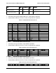
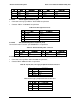
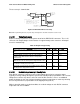
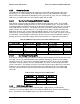
2.4.2.6 Hard Drive 12V rail configuration options
The following table shows the hard drive configuration options using the defined power
connectors. In some cases additional converter or ‘Y’ cables are needed.
Table 82. Hard Drive 12V rail configuration options
P8
P9
P10
P11
P5
P6
P7
1x4
1x4
1x4
1x4
1x5
1x5
1x4
18
3 x 2.5" 8xHDD BP
HDD1
8 x 2.5
HDD2
8 x 2.5
na
na
na
na
HDD3
8 x 2.5
2 x 3.5" 4xHDD
BP
HDD1
4x3.5
HDD1
4x3.5
peripheral bay
1 x 3.5" 8xHDD
BP
HDD1
8x3.5
na
na
peripheral bay
8 x 3.5" fixed
SATA
2xfixed
2xfixed
2xfixed
2xfixed
peripheral bay
8 x 3.5" fixed
SAS
2xfixed
2xfixed
2xfixed
2xfixed
peripheral bay