Intel® Server Chassis P4000S Family Intel® Server System P4304BT Series Quick Installation User's Guide Thank you for buying an Intel® Server Chassis or System. The following information will help you assemble your Intel® Server Chassis and install components. If you are not familiar with ESD [Electrostatic Discharge] procedures used during system integration, see the complete ESD procedures described in your Service Guide. This guide and other supporting documents are located on the web at: http://www.
Warning Warning Caution Tools Required Read all caution and safety statements in this document before performing any of the instructions. Also see the Intel ® Server Board and Server Chassis Safety Information document at: http://support.intel.com/support/ motherboards/server/sb/cs-010770 .htm for complete safety information. Installation and service of this product to be performed only by qualified service personnel to avoid risk of injury from electrical shock or energy hazard.
Table of Contents Chassis Overview .............................................................................................................................. 1 Intel® Server Chassis P4304XXSFCN ...................................................................... 1 Intel® Server Chassis P4304XXSHCN ..................................................................... 1 General Installation Process ........................................................................................................
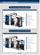
Chassis Overview Intel® Server Chassis P4304XXSFCN Chassis Features and Components A A B C D E F G H I J K L M E B K F G H C L I M D J 365-W Fixed Power Supply I/O Ports Alternate RMM4 Knockout PCI Add-in Board Slot Covers AC Input Power Connector 92mm Chassis Rear Fan Alternate Serial Port Knockout A Kensington* Cable Lock Mounting Hole Padlock Loop Alternate RMM4 Knockout Front Control Panel 5.
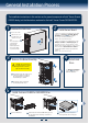
General Installation Process The installation instructions in this section are for general components of Intel® Server Chassis P4000S family, but the illustrations are based on the Intel® Server Chassis P4304XXSFCN. 1 2 Remove the Side Cover A Remove the screws. B Slide the side cover back and lift the cover outward to remove it. Note: A non-skid surface or a stop behind the chassis may be needed to prevent the chassis from sliding on your work surface.
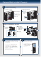
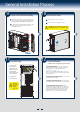
General Installation Process 6 Install PCI Card Assembly A. Install PCI Card Guide B. Install PCI Add-in Boards NOTE: Only needed when full length PCI card is plugged. A A Insert tabs on left side of PCI Card Guide into slots in chassis. B Secure the PCI Card Guide with the screws . A Remove the PCI slot shield by pushing the shield out from inside the chassis. A B Install PCI Card Assembly ... Continued B 7 From inside of chassis,press open the back panel PCI add-in board retention device.
General Installation Process 9 10 Install Side Cover Install Front Bezel Assembly A Engage three plastic bezel hooks into the raised metal slots at the chassis edge. Keep the right edge of front bezel align tightly with the right edge of the Chassis. B Rotate the bezel assembly toward the chassis and latch the two plastic tabs on the left side of the bezel assembly to the chassis. B A Slide the chassis cover on the chassis. B Secure the chassis cover with the screws .
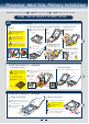
Processor, Heat Sink, Memory Installation Follow below Instructions for step 2 on page 2, then return to step 3 on page 2 when finish this section. Intel® Server Board S1200BT Series 2a Install the Processor(s) A. Open the Socket Lever B. Open the Load Plate Cautions: A A When removing the protective cover, DO NOT TOUCH the gold socket pins. B To avoid damage, DO NOT DROP the cover onto the socket pins or components. C Push the lever handle down and away from the socket to release it.
Processor, Heat Sink, Memory Installation 2b Install Active Heat Sink(s) CAUTION: The heat sink has thermal interface material (TIM) on the underside of it. Use caution so that you do not damage the thermal interface material. Use gloves to avoid sharp edges. 3 Note: Heatsink styles may vary 2 Use the following procedure to install an active heat sink to your server board: A 2c B E Repeat B-D for each fastener in the numerical order shown at left.
Hard Drive Installation Follow below Instructions for step 4 on page 2, then return to step 5 on page 2 when finish this section. Fixed Hard Drive Installation 4 A. Remove the EMI shield B. Install the Hard Drive C. Install the EMI shield A A B C B A Lift the EMI shield. B move EMI shield outward from the chassis. A B B C Secure the HDD on the HDD carrier tray with screws. Insert the HDD carrier tray into chassis. A Fit the edges of the EMI Shield against the sides of the chassis.
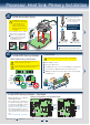
Server Board Cabling Connections Follow below Instructions for step 7 on page 3, then return to step 8 on page 3 when finish this section. Intel® Server Board S1200BTL Intel® Server Board S1200BTL To Intel® Server Chassis P4304XXSFCN Ext USB ODD HDD ODD NOTE : The Chassis mechanically supports up to three 5.25" ODDs. NOTE: Return to step 8 on page 3 when finish this section.
Server Board Cabling Connections Follow below Instructions for step 7 on page 3, then return to step 8 on page 3 when finish this section.
Server Board Cabling Connections Follow below Instructions for step 7 on page 3, then return to step 8 on page 3 when finish this section.
Front Panel Controls and Indicators Front Panel Controls and Indicators I A A Reservation(Optional VGA/Serial Port) B USB Connectors C ID Button with ID LED Integrated B C D NMI Button E NIC LED F System Reset Button 11 D E F G H G System Status LED H System Power Button with Power LED I HDD Activity LED
G23642-002