
Technical Product Specification


4x3.5” Hot-Swap Back Plane (HSBP) Intel
®
Server Chassis P4000S Family TPS
Intel order number G22850-006 Revision 1.5
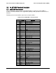
80
Pin
Pin Name
Signal Name
36
P0[2]
TP_THERM_N
37
P0[4]
TP_LED_HDD_FAULT4_N
38
P0[6]
TP_LED_HDD_FAULT6_N
39
Vdd
P3V3
40
P0[7]
TP_LED_HDD_FAULT7_N
41
P0[5]
TP_LED_HDD_FAULT5_N
42
P0[3]
TP_P0_3
43
P0[1]
TP_P0_1
44
P2[7]
FM_HDD_PRSNT3
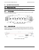
5.2.2 SGPIO Functionality
The 4x 3.5" HSBP supports a SFF-8485 compliant SGPIO interface. It is used to activate the
HDD status LED as well is monitored by the microcontroller for generating fault, identifying, and
rebuilding registers that in turn are monitored by the baseboard BMC for generating
corresponding SEL events.
SGPIO uses a 5pin header; this is to incorporate a ground conductor as an SI improvement
over previous generation products and based on measurement data indicating add the ground
is strongly recommended. The 5pin connector will be consistent with other HSBPs, in this way
cable commonality is improved.
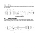
5.2.3 I
2
C Functionality
The microcontroller has a master/slave I
2
C connection to the baseboard BMC. The
microcontroller is not an IPMB compliant device. The BMC will generate SEL events by
monitoring registers on the HSBP microcontroller for drive presence, fault, and RAID rebuild in
progress.
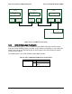
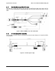
I
2
C uses a 5pin connector; this is to add two additional address bits. This connector is keyed
differently than the 5pin SGPIO connector. The 4x3.5" HSBP architecture is setup to support up
to three HSBPs even though the 4x 3.5" HSBP is currently only indented to support up to two of
them in the Intel
®
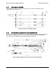
Server Chassis P4000S, P4000M, and P4000L family. Two pins on the I
2
C
header are used to indicate HSBP address. Below is a figure on how the addressing is
recommended for up to three HSBPs.