
Technical Product Specification


Intel
®
Server Chassis P4000S Family TPS Standard Front Panel
Revision 1.5 Intel order number G22850-006
75
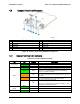
LED
Color
Condition
What It Means
Activity/Link
(LAN 1-2 for Intel
®
Server Board
S1200BT)
Green
Blink
LAN access.
Off
Idle.
Chassis
Identification
Blue
On
Front panel chassis ID button pressed.
Blue
Blink
Unit selected for identification from the software.
Off
No identification.
Note:
This is dependent on server board support. Not all server boards support all features.
For
additional details about control panel functions supported for a specific board, refer to the
individual server board specifications.
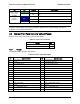
4.4 Common Front Panel Connector List and Pinouts
Below is a list of the connectors needed for this board.
Table 95. Connectors for Boards
Function
Qty
RA 2x15 FP
1
RA 1x2 Chassis Intrusion
1
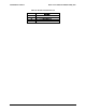
4.4.1 Pinouts
The following table describes the pinouts:
Table 96. Pinouts Signal Description
Pin
Signal Description
Pin
Signal Description
1
Power LED Anode
2
Front Plane Power (P3V3_STBY)
3
Key Pin
4
System ID LED Anode
5
Power LED Cathode
6
System ID LED Cathode
7
HDD Activity LED Anode
8
System status LED1 Cathode (Green)
9
HDD Activity LED Cathode
10
System status LED2 Cathode (Amber)
11
Power Switch
12
NIC_1 Activity LED Anode
13
Power Switch (GND)
14
NIC_1 Activity LED Cathode
15
Reset Switch
16
SMBus* SDA
17
Reset Switch (GND)
18
SMBus* SCL
19
System ID Switch
20
Chassis Intrusion
21
1-wire Temp Sensor (unused)
22
NIC_2 Activity LED Anode
23
NMI to CPU Switch
24
NIC_2 Activity LED Cathode
25
Key Pin
26
Key Pin
27
NIC_3 Activity LED Anode
28
NIC_4 Activity LED Anode
29
NIC_3 Activity LED Cathode
30
NIC_4 Activity LED Cathode
Note: Pin 1~24 is compatible with SSI spec.