
Technical Product Specification


Standard Front Panel Intel
®
Server Chassis P4000S Family TPS
Intel order number G22850-006 Revision 1.5
74
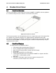
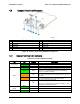
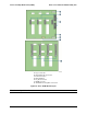
4.3 Common Front Panel Placement
Description
Description
A
Unstuffable ID Button with ID LED
F
Status/Fault LED
B
NMI Button
G
Power Button with power LED
C
LAN1 LED
H
LAN2 LED
D
LAN3 LED
I
LAN4 LED
E
Reset Button
J
HDD activity LED
Figure 41. Common Front Panel LED/Button Arragement
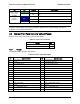
4.3.1 Common Front Panel LED Functionality
Table 94. Front Panel LED Functionality
LED
Color
Condition
What It Means
Power/Sleep
Green
On
Power on or S0 sleep.
Green
Blink
S1 sleep or S3 standby only for workstation baseboards.
Off
Off (also sleep S4/S5 modes).
Status
Green
On
System ready/No alarm.
Green
Blink
System ready, but degraded: redundancy lost such as PS or
fan failure; non-critical temp/voltage threshold; battery
failure; or predictive PS failure.
Amber
On
Critical alarm: Voltage, thermal, or power fault; CPU
missing; insufficient power unit redundancy resource offset
asserted.
Amber
Blink
Non-Critical failure: Critical temp/voltage threshold; VDR hot
asserted; min number fans not present or failed.
Off
AC power off: System unplugged.
AC power on: System powered off and in standby, no prior
degraded\non-critical\critical state.
Global HDD
Activity
Green
Blink
HDD access.
Off
No access and no fault.
LAN 1-4
Green
On
LAN link/no access.