
Technical Product Specification


Chassis Power Sub-system Intel
®
Server Chassis P4000S Family TPS
Intel order number G22850-006 Revision 1.5
56
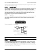
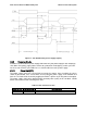
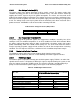
Figure 33. Implementation of the Power Ok Circuits
2.3.6.3 SMBAlert# Signal
This signal indicates that the power supply is experiencing a problem that the user should
investigate. This shall be asserted due to Critical events or Warning events. The signal shall
activate in the case of critical component temperature reached a warning threshold, general
failure, over-current, over-voltage, under-voltage, failed fan. This signal may also indicate the
power supply is reaching its end of life or is operating in an environment exceeding the specified
limits. This signal is to be asserted in parallel with LED turning solid Amber or blink Amber.
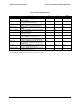
Table 67. SMBAlert# Signal Characteristics
2.3.7 Thermal CLST
The power supply shall assert the SMBAlert signal when a temperature sensor crosses a
warning threshold. Refer to the Intel
®
Common Hardware and Firmware Requirements for
CRPS Power Supplier for detailed requirements.
2.3.8 Power Supply Diagnostic “Black Box”
The power supply shall save the latest PMBus* data and other pertinent data into nonvolatile
memory when a critical event shuts down the power supply. This data shall be accessible from
the SMBus* interface with an external source providing power to the 12Vstby output.
Q2
2N4401
PWOK out
PWOK in
Q1
2N4401
12V
3.3VSB
R2
20
R4
820
R3
10k
R1
10k
Signal Type (Active Low)
Open collector/drain output from power supply. Pull-
up to VSB located in system.
Alert# = High
OK
Alert# = Low
Power Alert to system
MIN
MAX
Logic level low voltage, Isink=4 mA
0 V
0.4 V
Logic level high voltage, Isink=50 A
3.46 V
Sink current, Alert# = low
4 mA
Sink current, Alert# = high
50 A
Alert# rise and fall time
100 s