
Technical Product Specification


Intel
®
Server Chassis P4000S Family TPS Chassis Power Sub-system
Revision 1.5 Intel order number G22850-006
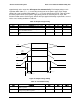
45
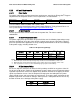
Pin
Name
Pin
Name
A1
GND
B1
GND
A2
GND
B2
GND
A3
GND
B3
GND
A4
GND
B4
GND
A5
GND
B5
GND
A6
GND
B6
GND
A7
GND
B7
GND
A8
GND
B8
GND
A9
GND
B9
GND
A10
+12V
B10
+12V
A11
+12V
B11
+12V
A12
+12V
B12
+12V
A13
+12V
B13
+12V
A14
+12V
B14
+12V
A15
+12V
B15
+12V
A16
+12V
B16
+12V
A17
+12V
B17
+12V
A18
+12V
B18
+12V
A19
PMBus* SDA
B19
A0 (SMBus* address)
A20
PMBus* SCL
B20
A1 (SMBus* address)
A21
PSON
B21
12V stby
A22
SMBAlert#
B22
Cold Redundancy Bus
A23
Return Sense
B23
12V load share bus
A24
+12V remote Sense
B24
No Connect
A25
PWOK
B25
Compatibility Check pin*
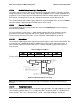
Note: Refer to the Common Hardware and Firmware Requirements for CRPS Power Supplies Specification.
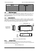
2.3.1.2 Handle Retention
The power supply shall have a handle to assist extraction. The module shall be able to be
inserted and extracted without the assistance of tools. The power supply shall have a latch
which retains the power supply into the system and prevents the power supply from being
inserted or extracted from the system when the AC power cord is pulled into the power supply.
The handle shall protect the operator from any burn hazard through the use of the Intel
Corporation Industrial designed plastic handle or equivalent Intel approved material.
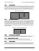
2.3.1.3 LED Marking and Identification
The power supply shall use a bi-color LED; Amber and Green. The following table shows the
LED states for each power supply operating state and the LED’s wavelength characteristics.
Refer to the Intel
®
LED Wavelength and Intensity Specification for more details.