OPEN (660) 120/140/150 II 12.1" /14.1" /15.1" TFT Intel® Celeron/Pentium® III Multimedia Open-frame Panel PC User’s Manual (version 2.
Copyright Notice This document is copyrighted, 2001 by the Manufacturer. The information provided in this document has been carefully checked and is accurate at the time of publication. However, the Manufacturer assumes no responsibility for any infringements of patents or other rights of third parties that may result from its use.
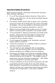
Unpacking After unpacking the OPEN (660) system carton, check and see if the following items are included and in good condition. l l OPEN (660) 120/140/150 II main system x 1 Accessories - Power cord External FDD cable External IDE cable External FDD & HDD power cable User manual diskette in .
Important Safety Precautions Before getting started, read these instructions and save them for later reference. 1. Turn off the computer before cleaning. Clean with a damp or dry cloth only. Do not spray any liquid cleaner on screen directly. 2. The power outlet socket used to plug in the computer power cord must be located near the system and easily accessible. Do not use outlets on the same circuit of the systems that regularly switched on and off. 3.
10. The openings on the computer enclosure are for the cabin ventilation to prevent the computer from overheating. DO NOT COVER THE OPENINGS. 11. The brightness of the flat panel display will decrease with use. However, hours of use will vary depending on the application environment. 12. If the computer is equipped with a touch panel, avoid using sharp objects to operate the touch panel. Scratches on the touch panel may cause malcalibration or non-function to the panel. 13.
Table of Contents 1. INTRODUCTION............................................. 1-1 1.1. GENERAL INFORMATION ..................................1-2 1.2. WHAT COVERS IN THIS MANUAL.........................1-3 1.3. SPECIFICATIONS ...........................................1-5 1.4. DIMENSIONS ...............................................1-9 1.5. OPTIONAL MODULES & ACCESSORIES ................ 1-11 1.5.1. Touchscreen Module ............................. 1-11 2. IDENTIFYING THE SYSTEM COMPONENTS ... 2-13 2.1.
4. SYSTEM HARDWARE INSTALLATION ........... 4-37 4.1. INSTALLING THE CPU ................................... 4-39 4.2. INSTALLING THE SDRAM MEMORY MODULE ........ 4-40 4.3. INSTALLING THE HDD .................................. 4-41 4.3.1. OPEN 120/140 2.5" HDD Installation ...... 4-41 4.3.2. OPEN 150 3.5" HDD Installation ............ 4-42 4.4. INSTALLING THE FDD................................... 4-43 4.4.1. External FDD connection ....................... 4-43 4.4.2. Internal FDD installation for OPEN 150.
6.2. LOCATING JUMPERS & CONNECTORS ................. 6-63 6.2.1. Jumpers & Jumper Setting..................... 6-64 6.2.1.1. DOC 2000 Address Setting (JP9)....... 6-65 6.2.1.2. COM 2 RS-232/485 Setting (JP3,5,6) 6-65 6.2.1.3. CMOS Clear Setting (JP4) ................ 6-66 6.2.1.4. LCD Power Setting (JP1) .................. 6-66 6.2.2. Connectors & Pin Assignment................. 6-67 6.2.2.1. CN12: Main Power Connector ........... 6-68 6.2.2.2. CN2/IDE1: IDE Connector................ 6-69 6.2.2.3.
8. SOFTWARE DRIVERS INTRODUCTIONS ..... 8-103 8.1. ETHERNET DRIVERS ................................... 8-104 8.1.1. Features............................................ 8-104 8.2. OPEN (660) PCI XGA SETUP ................... 8-105 8.3. AUDIO SETUP .......................................... 8-106 8.4. DRIVER INSTALLATION ................................ 8-107 9. TOUCHSCREEN........................................... 9-109 9.1. MICROTOUCH TOUCH DRIVER INSTALLATION ...... 9-110 9.1.1.
User Manual version 2.1 1. INTRODUCTION This chapter provides background information and detail specification on the OPEN (660) system.
User Manual version 2.1 1.1. General Information The information revolution happened from the mid ’90 inaugurated a new competitive era where consumer computing technology was exploited to business operation more quickly than ever before. Many enterprises from our life related industries such as POS, POI, KIOSK, Banking, Medical to the high-tech Telecom, Aerospace, Semiconductor … etc. all are eager or forced to automate their industries with PCs in order to thrive in this new age.
User Manual version 2.1 1.2. What Covers in this Manual This handbook contains most information you need to set up and use this computer. You do not need to read everything in this handbook to use the OPEN (660) II system. For a quick start, see the following chapter summaries; Chapter 1 (the current chapter) provides background information and detail specification on the OPEN (660) 120/140/150 II. This chapter also details the optional modules and accessories of the OPEN (660) system.
User Manual version 2.1 Appendix A details the 12.1”/14.1”/15.1” LCD specifications. Appendix B explains how to program the watchdog timer. Appendix C introduces the DiskOnChip installation. Appendix Appendix Appendix Appendix 1-4 D introduces the system I/O ports. E explains the RS-485 programming. F explains the first MB memory map. G provides the specifications for the built-in power supply.
User Manual version 2.1 1.3. Specifications SYSTEM Flat Panel u u u OPEN (660) 120: Viewing angle Luminance (cd/m2) 12.1” color TFT, 800*600 100 130 or above, optional high-brightness model Simultaneous mode OPEN (660) 140: Viewing angle Luminance (cd/m2) yes 14.1” color TFT, 800*600 100 150 or above, optional high-brightness model Simultaneous mode OPEN (660) 150: Viewing angle Luminance (cd/m2) yes 15.
User Manual version 2.
User Manual version 2.
User Manual version 2.1 u Front panel size (Aluminum frame) OPEN (660) 120A: 380*310 OPEN (660) 140A: 405*330 OPEN (660) 150A: 448*371 Mounting u u Panel mount with mounting kits To KIOSK enclosure Specifications are subject to change without notice.
User Manual version 2.1 1.4.
User Manual version 2.
User Manual version 2.1 1.5. Optional Modules & Accessories 1.5.1. Touchscreen Module The OPEN (660) system features a touchscreen module for mounting a touchscreen for keyboardless operation. The special designed touchscreen module can firmly hold the touch panel and the LCD panel together to prevent dust and water in.
User Manual version 2.1 Dimension (unit: mm) : OPEN 150 touchscreen module Caution: The connection point of the touchscreen and its cables is very fragile. Do not take the touchscreen by dragging its cable or pull the cables at any time; this may lead inaccurate calibration or non-function to the touchscreen.
User Manual version 2.1 2. IDENTIFYING THE SYSTEM COMPONENTS Before getting started, take a moment to familiarize yourself with the different parts and the I/O arrangement of the OPEN (660) 120/140/150 I.
User Manual version 2.1 2.1.
User Manual version 2.1 2.2.
User Manual version 2.1 2.3.
User Manual version 2.1 OPEN 150 I/O outlet 18 8 7 6 5 4 3 2 1 17 12 13 16 1. USB 15 9 10 14 11 2. ETHERNET (RJ-45) 3. PS/2 MOUSE 4. PS/2 KB 5. LINE-IN 6. SPEAKER-OUT 7. MIC-IN 8. VGA 9. COM 1 10. COM 2 11. COM 3 12. COM 4 13. EXTERNAL FDD 14. PRINTER PORT 15. EXTERNAL IDE PORT 16. +5V/12V POWER 17. AC PORT INLET OPEN (660) 120/140/150 18.
User Manual version 2.1 2.4. System Major Parts The following diagram shows the system major parts that make up the OPEN (660) 120/140/150 II.
User Manual version 2.1 2.5. System Setup for the First-time Use To set up the OPEN (660) system for the first-time use, you should have the following items ready. The items are either in the accessory box or available in any computer stores. u u u 110V or 220V power cord PS/2 or AT keyboard PS/2 or serial mouse 2.5.1. Installation Procedures The OPEN (660) system can be powered either by an AC electrical outlet (90 ~ 240V, 50 ~ 60Hz) or by DC power source (9 ~ 132 VDC).
User Manual version 2.1 2.5.2. Running the BIOS Setup If you are a commercial user, the OPEN (660) 120/140/150 should have been properly set up and configured by your dealer. You may still find it necessary to change the system configuration information. In this case, you need to run the system’s BIOS setup program. Under the following conditions, the CMOS settings are to be changed; 1. The system is starting for the first time 2. The hardware devices attached to the OPEN (660) system have been changed 3.
User Manual version 2.1 2.5.3. Operating System and Driver Installation The OPEN (660) system is not equipped with an operating system when delivered from the original manufacturer. If you are a commercial user, the system is likely to have been pre-installed proper operating system and software drivers by your dealer or system integrator.
User Manual version 2.
User Manual version 2.1 3. MOUNTING OPTIONS To OPEN (660) system is designed for universal mounting to fit into different system enclosures for various environmental applications. This chapter highlights the steps of different mounting alternatives of the OPEN (660) system.
User Manual version 2.1 3.1. Different Front Bezels The standard OPEN (660) systems provide 3 kinds of front bezel for different environmental applications. 3.1.1. OPEN (660) system with Small Bezel The OPEN (660) 120/140/150 S is OPEN (660) system with small bezel. The front bezel size is identical to the computer’s chassis size.
User Manual version 2.1 3.1.2. OPEN (660) system with Big Bezel The OPEN (660) 120/140/150 B is OPEN (660) system with big bezel. The front bezel size is larger than the computer’s chassis size. Front bezel size (Big panel) OPEN (660) 120B: 380*310 mm OPEN (660) 140B: 405*330 mm OPEN (660) 150B: 448*371 mm The type of frame is mainly designed for panel mounting or for KIOSK integration when the KIOSK enclosure is of flat surface and allows the computer to be fixed to the KIOSK enclosure directly.
User Manual version 2.1 3.1.3. Aluminum Alloy Frame The OPEN (660) 120/140/150 A is OPEN (660) system with an aluminum alloy frame. The aluminum alloy frame is mainly designed for panel mounting. It not only strengthens the system’s framework but also beautifies the system outlook when the system is panel mounted.
User Manual version 2.1 3.2. Metal Fixtures The OPEN (660) system provides 2 sets of metal fixture for system mounting. In most occasions, special metal fixtures need to be designed to mount the OPEN (660) system to different system enclosures. 3.2.1. Metal Fixture A A set of metal fixture A is provided to fix the system enclosure and the computer chassis together. To use the metal fixtures, follow the instructions below; 1.
User Manual version 2.1 3.2.2. Metal Fixture B Another set of metal fixture B is also provided to fix the system enclosure and the computer chassis together. The metal fixture B is mainly used in panel mounting application, i.e. when the touchscreen is mounted outside of the system enclosure while the computer itself is mounted from inside. Use the provided screws to firmly fix the system enclosure between the touchscreen module and the computer chassis with metal fixture B. 22.7 25 25 22.
User Manual version 2.1 3.3. Front Mounting The OPEN system can be mounted to the system enclosure from the enclosure’s front side. Two conditions are introduced in this section. 3.3.1. Front Mounting with Touchscreen Module If the OPEN system comes with a touchscreen module, to mount the computer to the system enclosure from the front side, follow the steps below; Touchscreen System enclosure module Fixture A 1.
User Manual version 2.1 3.3.2. Front Mounting without Touchscreen Module If the application does not need the installation of the touchscreen module, then there are two methods to mount the OPEN system from the system enclosure’s front side. Method 1 with bronze stick 1. Cut a window of the same size of the OPEN system’s flat panel display on the system enclosure and make necessary fixed holes on it. System enclosure Bronze stick 2.
User Manual version 2.1 Method 2 with metal fixture A 1. Cut a window of the same size of the OPEN 120/140/150’s flat panel display on the system enclosure and make necessary fixed holes on it. 2. Before inserting the OPEN system into the system enclosure, make sure all the hardware jumpers and necessary software are installed. 3. Get a glass or acrylic transparent piece of the size slighter larger than the cut window.
User Manual version 2.1 3.4. Rear Mounting To fit into special environmental applications, the OPEN system can be also mounted to the system enclosure from the enclosure panel’s rear side. Two conditions are introduced in this section.
User Manual version 2.1 3.4.1. Fixing on the System Enclosure’s front panel Refer to the following figure and follow the steps below. 1. Cut a window of the same size of the OPEN system’s panel display on the System enclosure system enclosure. The system enclosure should come with some Bracket on the brackets. To make the brackets, System enclosure please refer to the diagram of the Fixture A dimension and fixing holes of the OPEN system in Sec. 1.4.
User Manual version 2.1 3.4.2. Fixing on the System Enclosure’s back panel 1. Cut a window of the same size of Touchscreen module the OPEN system’s panel display on the system enclosure. The Fixture A system enclosure should come System enclosure with some brackets. To make the brackets, please refer to the Fixture on the system enclosure diagram of the dimension and fixing holes of the OPEN system in Sec. 1.4. Fix the brackets on the 4 sides of the enclosure’s back panel.
User Manual version 2.1 If the system enclosure is not limited in thickness, then to mount the OPEN system on the system enclosure’s front panel is recommended for easy installation and maintenance. However, if the system enclosure is limited in space, then it is suggested to mount the OPEN system on the system enclosure’s back panel to increase the installation yield rate.
User Manual version 2.1 3.5. Panel Mounting The panel mounting is the easiest method among all mounting alternatives. However, this will expose the aluminum alloy frame or the touchscreen module frame outside of the system enclosure unless a special frame is designed to cover it. Follow the instructions below for panel mounting. 1. Cut a window of the same size of the OPEN system panel display on the system enclosure. 2.
User Manual version 2.1 4. SYSTEM HARDWARE INSTALLATION This chapter overviews the installation of the OPEN (660) II system internal components and devices.
User Manual version 2.1 The OPEN (660) 120/140/150 II consists of a Celeron/ Pentium ® III embedded little board with an adequate CPU and relevant SDRAM on it. The system control board and other internal devices such as expansion card, HDD and power supply are already housed in a plastic rear cover. The system’s performance depends on the installed CPU and the capacity of the system memory and hard disk drive. In some circumstances, you might intend to upgrade or maintain the system.
User Manual version 2.1 4.1. Installing the CPU The OPEN (660) 120/140/150 II system control board can adapt Intel Celeron and Pentium III CPU. It can support Intel Socket 370 CPU from Celeron ® PPGA/FCPGA/66MHzz to Pentium ® III FCPGA/100MHz (Intel 440BX). The system controller provides one 370-pin socket (Socket 370). The CPU must come with a CPU fan to avoid overheating. The Celeron CPU and P III CPU will request different kinds of CPU fans due the difference on the CPUs’ mechanism.
User Manual version 2.1 4.2. Installing the SDRAM Memory Module The OPEN (660) 120/140/150 II system control board provides 1 x 168-pin DIMM socket, able to support SDRAM memory from 32MB up to 256MB. To install the memory module, follow the instructions below; 1. 2. 3. Detach and remove the rear cover. Find the 168 pin DIMM socket on the motherboard There are two white eject levers at each end of the DIMM socket. Push them outward until they separate from the two vertical posts. 4.
User Manual version 2.1 4.3. Installing the HDD 4.3.1. OPEN (660) 120/140 2.5" HDD Installation The OPEN (660) 120/140 provides enough space to build in a 2.5” hard disk drive in the computer chassis. If the user intends to attach a 2.5” hard disk or remove the existing device for repair or for a higher-capacity one, the following figure shows you the way to install an internal HDD. 1. Detach and remove the rear cover. The HDD module is located at the side of the system compartment 2.
User Manual version 2.1 4.3.2. OPEN (660) 150 3.5" HDD Installation The OPEN (660) 150 provides enough space to build in a 3.5” hard disk drive in the computer chassis. If the user intends to attach a 3.5” hard disk or remove the existing device for repair or for a higher-capacity one, the following figure shows you the way to install an internal HDD. 1. Detach and remove the rear cover. 2. Remove the CD-ROM/FDD module. 3. Take out the FDD/IDE board 4. Remove the whole HDD module. 5. Install the 3.
User Manual version 2.1 4.4. Installing the FDD The OPEN (660) 120/140/150 II can connect to an external floppy disk drive. 4.4.1. External FDD connection 1. Use the provided 15-34 pin FDD cable to connect to the system's 15-pin FDD D-sub connector located at the rear side of the cover. FDD cable 2. Connect the other end of the FDD cable to a standard 3.5” FDD. Match pin 1 of the floppy disk drive and pin 1 of the cable. 3.
User Manual version 2.1 4.4.2. Internal FDD installation for OPEN 150 Aside from connecting to an external FDD, the OPEN (660) 150 can also accommodate an internal slim type FDD, depending on the system requirement. The floppy disk drive used in the OPEN 150 II is a slim type FDD widely used in notebook computers. To install the floppy disk drive to the OPEN 150, refer to the following steps below: 1. Detach and remove the rear cover. 2. There is an FDD/CD-ROM bracket holding the FDD. Remove the bracket.
User Manual version 2.1 4.5. Installing the CD-ROM drive The OPEN 120/140/150 II can connect to an external CD-ROM via the system's external IDE connector. 4.5.1. External CD-ROM connection 1. Use the provided 40 pin IDE cable to connect to the system IDE connector located at the rear side of the cover. 2. Connect the other end of the IDE cable to a standard CD-ROM drive 3.
User Manual version 2.1 4.5.2. Installing Internal CD-ROM for OPEN 150 Aside from connecting to an external CD-ROM, the OPEN 150 can also accommodate an internal slim type CD-ROM, depending on the system requirement. The CD-ROM drive used in the OPEN 150 II is not the common 5.25” CD-ROM drive seen in computer stores. Rather, it is a slim type CD-ROM widely used in notebook computers. To install a compact CD-ROM to the OPEN 150 system, refer to the following figure and follow the steps below: 1.
User Manual version 2.1 4.6. Expansion Slot The OPEN system provides a free PCI/ISA expansion slot. Via the specially designed riser card, the system can accommodate either an ISA or PCI expansion device. Due to the space limitation, only one PCI or ISA device can be inserted in the expansion at a given time. Also due to the internal space limitation, only a compact expansion card can be inserted. The expansion card size can not exceed 160*120 mm (L*W).
User Manual version 2.
User Manual version 2.1 5. I/O CONNECTION This chapter describes the OPEN (660) system I/O ports and how to use the I/O interface to connect to external devices.
User Manual version 2.1 The user can use the I/O interfaces located at the rear side of the chassis to connect external peripheral devices, such as a mouse, a keyboard, a monitor, serial devices or parallel printer…etc. Before any connection, make sure that the computer and the peripheral devices are turned off. 5.1. VGA Interface The OPEN (660) 120/140/150 II has a 15-pin analog RGB connector located at the rear side of the chassis.
User Manual version 2.1 5.2. COM Ports x 4 The OPEN (660) 120/140/150 (+) II features with four onboard COM ports located at the rear side of the chassis, ready to connect to a wide range of serial devices. COM1, COM3 and COM4 are RS-232 and COM2 is RS-232/485, selected via jumper setting. Each COM port is with +5V/+12V power capabilities on pin 9, providing easy accommodation to a broad range of serial devices. The COM port 5V/12 power is selected via jumper setting on the I/O board.
User Manual version 2.1 If a touchscreen module is installed, for factory default setting, its controller will occupy COM3. COM1 to COM4 are all D-SUB 9-pin connectors. To connect to any serial device; follow the procedures below; 1. Turn off the OPEN system and the serial devices. 2. Attach the interface cable of the serial device to the 9-pin D-SUB serial connector. Be sure to fasten the retaining screws. 3. Turn on the computer and the attached serial devices. 4.
User Manual version 2.1 5.3. Parallel Port The OPEN (660) system can support the latest EPP and ECP parallel port protocols. It can be used to connect to a wide array of printers, ZIP drive, parallel scanner and any other parallel devices. The printer interface on the OPEN (660) system is a 25-pin female D-SUB connector located on the bottom side. To connect any parallel device, just plug in the male connector of the parallel device to the 25-pin female D-SUB connector. 5.4.
User Manual version 2.1 5.5. USB Ports The OPEN (660) system also provides two USB ports to connect to external USB devices. Before connecting to the USB devices, remember to install the device driver first. 5.6. Audio Interface The audio interface contains three jacks, microphone-in, line-in and speaker-out. The microphone-in jack is used to record sound or voice by connecting to an external microphone.
User Manual version 2.1 5.7. External FDD (DB-15) The OPEN (660) 120/140 II does not build in any floppy disk drive into the main system. Rather, it provides a FDD interface located at the rear panel. The OPEN (660) 150 can either use an internal floppy disk drive or to external type. When the OPEN (660) system is using external floppy disk drive, an external FDD cable is provided to connect a standard 3.5” FDD to the system for system O/S and application software installation.
User Manual version 2.1 5.8. +5V/12V DC-Out The OPEN (660) system provides a +5V/12V DC-out connector. It is used to provide necessary power source for some external devices. For example, if an external floppy disk drive is attached to the system, it will need +5V power source from the system. A power cable for the external floppy disk drive is already provided for this connection. For other devices, you might need to make your own power cable for the connection. 5.9.
User Manual version 2.1 6. SYSTEM CONTROL BOARD The system controller used in the OPEN (660) system is a Celeron/Pentium ® III multimedia embedded little board, PC 660A3. This chapter provides detail introduction of the system engine.
User Manual version 2.1 6.1. Introduction This section provides background information and detail specification on the OPEN (660) 120/140/150 II system engine, PC 660A3. Sections include: ² General Information ² Features ² Specification ² Board placement & Dimension 6.1.1. General Information The PC 660A3 is an Intel Celeron/ Pentium ® III (Socket 370) multimedia mini board.
User Manual version 2.1 6.1.2.
User Manual version 2.1 6.1.3. Specifications PC 660A3: Multimedia Intel Celeron/Pentium ® III Embedded Mini Board with XGA, Flat panel, Ethernet & Audio Interface u CPU: Intel Celeron/Pentium ® III (Socket 370) − Intel Celeron ® PPGA/FCPGA/66MHzz − Intel Pentium ® III FCPGA/100MHz u System Chipset: Intel 440BX or the equivalent chipset u System BIOS: Award PnP Flash BIOS u System Memory: Equipped with one DIMM socket to support (32MB, 64MB, 128MB, 256MB) 168-pin 3.3V SDRAM SPD (Special Presence Detect).
User Manual version 2.1 u u u u Watchdog Timer: 16 time intervals Green Function: APM 1.
User Manual version 2.1 6.1.4. Board Placement & Dimension The PC 660A3 dimension and layout is shown below; 1 1 CN6 5V JP10 Reserve 3V JP1 J5=ON Celeron/Coppermine CN1 Socket 370 CPU 1 CN12 CN3 J3=ON JP7 1-2 66M 100M JP13 JP12 4 3 2 1 OFF OFF IDE1 3-4 OFF ON JP7 JP12,13 Reserve 12V JP4 CLR DIMM1 203.2 JP8 198.12 CN4 D000 FDC1 D800 JP9 CN2 422 422 JP5 JP6 232 232 422 JP3 232 U4 J2 CN10 CN9 CN7 CN8 CN5 135.89 146.
User Manual version 2.1 6.2. Locating Jumpers & Connectors The PC 660A3 is configured to match the needs of specific application by proper jumper settings. The onboard connectors link the PC 660A3 to external devices such as a hard disk, a floppy disk or a printer. The following figure helps you to locate all jumpers and connectors.
User Manual version 2.1 6.2.1. Jumpers & Jumper Setting The table below lists the function of each jumper. The related jumper settings are shown in the coming sections.
User Manual version 2.1 6.2.1.1. DOC 2000 Address Setting (JP9) D800 D000 D800 D000 Address D000~D7FF 6.2.1.2. Address D800~DFFF COM 2 RS-232/485 Setting (JP3, 5, 6) The PC 660A3 is a RS-232/485 serial port. JP3, JP5 and JP6 determine the specific port type. JP3 JP3 JP5 JP5 JP6 JP6 RS-232 mode RS-485 mode The RS-485 is software programmable. Please refer to APENDIX for the programming.
User Manual version 2.1 6.2.1.3. CMOS Clear Setting (JP4) Before setting “CMOS Clear”, remember to turn off the power supply to avoid damaging the computer board. After the setting, before turning on the power supply, set the jumper back to “3.6V Battery on”. JP4: CMOS Clear Setting 3.6V Battery On Clear CMOS CLR CLR default setting 6.2.1.4. 5V LCD Power Setting (JP1) 3.
User Manual version 2.1 6.2.2. Connectors & Pin Assignment The table below lists the function of each connector on the PC 660A3. Their corresponding pin assignments will be shown in the following sections.
User Manual version 2.1 6.2.2.1. CN12: Main Power Connector CN12 is a main power connector.
User Manual version 2.1 6.2.2.2. CN2/IDE1: IDE Connector CN2 is a 44-pin primary IDE connector and IDE1 is a 40-pin secondary IDE connector.
User Manual version 2.
User Manual version 2.1 6.2.2.3. CN3/CN1: Flat Panel Connector CN3 is a 50-pin flat panel connector and CN1 is a LCD backlight connector. Their pin assignments are listed below.
User Manual version 2.
User Manual version 2.1 6.2.2.4. CN5: IR and Serial Ports Connector The CN5 is a 40-pin IR and serial port connector. The PC 660A3 provides one IR port and four onboard serial ports with their signals mixed in one connector, CN5.
User Manual version 2.1 6.2.2.5. CN7: Digital I/O Connector The CN7 is a 10 pin digital I/O connector. CN7: DIO Connector pin assignment Pin # Signal Pin # Signal 1 OUT DATA0(SD4) 2 IN DATA0(SD0) 3 OUT DATA1(SD5) 4 IN DATA1(SD1) 5 OUT DATA2(SD6) 6 IN DATA2(SD2) 7 OUT DATA3(SD7) 8 IN DATA3(SD3) 9 GND 10 GND The PC 660A3 DIO can be used for the system’s simple automation control needs.
6.2.2.6. User Manual version 2.1 CN8: KB, MS, USB & PRT Connector The PC 660A3 provides one keyboard port, one PS/2 mouse port, two USB ports and one parallel port with their signal mixed in the CN8 connector.
User Manual version 2.1 6.2.2.7. CN10: CD Audio Input Connector Pin # Signal 1 AUXL 2 GND 3 GND 4 AUXR 4 3 2 1 6.2.2.8. CN9: Audio, Ethernet VGA CRT & LED Connector The CN9 is a 40-pin, dual-in-line pin header providing signals for audio, VGA CRT, Ethernet and LED.
User Manual version 2.1 6.2.2.9. CN6: Video Interface Connector The PC 660A3 provides a video interface connector (CN6) to support multimedia functions.
User Manual version 2.1 6.2.2.10. FDC1: FDD Connector The FDC1 is a 34-pin pin header FDD connector.
User Manual version 2.1 6.2.2.12. CN4: PCI/ISA Expansion Slot The PC 660A3 provides an ISA/PCI slot for ISA and PCI device expansion.
User Manual version 2.
User Manual version 2.
User Manual version 2.
User Manual version 2.1 7. AWARD BIOS SETUP The chapter describes how to set up BIOS configuration.
User Manual version 2.1 7.1. Award BIOS The Award BIOS ROM builds in a setup program, which allows the users to modify the basic system configuration such as the current date and time or the type of peripheral devices attached to the computer. Under the following conditions, the CMOS settings are to be changed; 4. The system is starting for the first time 5. The hardware devices attached to the systems have been changed 6. The CMOS memory has lost power and the configuration information has been erased.
User Manual version 2.1 7.2.
User Manual version 2.1 7.3. Getting Help 7.3.1. Main Menu The on-line description of the highlighted setup function is displayed at the bottom of the screen. Press to pop up a small help window that describes the appropriate keys to use and the possible selections for the highlighted item. To exit the Help Window, press .
User Manual version 2.1 7.4. AWARD BIOS Setup 7.4.1. AWARD BIOS Setup Main Menu Power on the computer and press immediately to run the AWARD BIOS setup. The setup main menu will appear on the screen. ROM PCI/ISA BIOS (2A69KHE9) CMOS SETUP UTILITY AWARD SOFTWARE, INC.
User Manual version 2.1 u STANDARD CMOS SETUP: This setup page includes all the items in standard compatible BIOS. u BIOS FEATURES SETUP: This setup page includes all the items of Award special enhanced features. u CHIPSET FEATURES SETUP: This setup page includes all the items of chipset special features. u POWER MANAGEMENT SETUP: This setup page includes all the items of Green function features. u PNP/PCI CONFIGURATION: This setup page includes all the configurations of PCI & PnP ISA resources.
User Manual version 2.1 7.4.2. Standard CMOS Setup If the STANDARD CMOS SETUP is selected from the main menu, the screen below will appear. This menu allows the users to configure the system components such as date, time, hard disk drive, floppy disk drive and display type. The system BIOS will automatically detect the memory size; therefore no setting is needed. ROM PCI/ISA BIOS (2A69K HE9) STANDARD CMOS SETUP AWARD SOFTWARE, INC.
User Manual version 2.1 u DATE The date format is , . day The day, from Sun to Sat, determined by the BIOS and is display-only month The month, Jan. through Dec. date The date, from 1 to 31 (or the maximum allowed in the month) year The year, from 1994 through 2079 u TIME The times format in . The time is calculated base on the 24-hour military-time clock. For example, 1 p.m. is 13:00:00.
User Manual version 2.1 u DRIVE A TYPE / DRIVE B TYPE The category identifies the types of floppy disk drive A or drive B that has been installed in the computer. None No floppy drive installed 360K, 5.25" 5.25 inch PC-type standard drive; 360K byte 1.2M, 5.25" 5.25 inch AT-type high-density drive; 1.2M byte (3.5 inch when 3 Mode is Enabled). 720K, 3.5" 3.5 inch double-sided drive; 720K byte 1.44M, 3.5" 3.5 inch double-sided drive; 1.44M byte 2.88M, 3.5" 3.5 inch double-sided drive; 2.88M byte u 12.
User Manual version 2.1 7.4.3. BIOS Features Setup If the BIOS FEATURES SETUP option is selected from the main menu, the screen below will appear. The following sample screen consists of the default values for OPEN (660). ROM PCI/ISA BIOS (2A69KHE9) BIOS FEATURES SETUP AWARD SOFTWARE, INC.
User Manual version 2.1 7.4.4. Chipset Features Setup If the CHIPSET FEATURES SETUP option is selected from the main menu, the screen below will appear. The following sample screen consists of the default values for OPEN (660). ROM PCI/ISA BIOS (2A69KHE9) CHIPSET FEATURES SETUP AWARD SOFTWARE, INC.
User Manual version 2.1 7.4.5. Power Management Setup If the POWER MANAGEMENT SETUP option is selected from the main menu, the screen below will appear. The following sample screen consists of the default values for OPEN (660). ROM PCI/ISA BIOS (2A69KHE9) POWER MANAGEMENT SETUP AWARD SOFTWARE, INC.
User Manual version 2.1 7.4.6. PnP/PCI Configuration If the PNP/PCI CONFIGURATION option is selected from the main menu, the screen below will appear. The following sample screen consists of the default values for OPEN (660). ROM PCI/ISA BIOS (2A69KHE9) PnP/PCI CONFIGURATION AWARD SOFTWARE, INC.
User Manual version 2.1 7.4.7. Load BIOS Defaults The LOAD BIOS DEFAULTS loads the default values to the system directly from the ROM. If the stored data generated by the Setup Program is gone, then when the computer is turned on, these default values will automatically load to the system. ROM PCI/ISA BIOS (2A69KHE9) CMOS SETUP UTILITY AWARD SOFTWARE, INC.
User Manual version 2.1 7.4.8. Load Setup Defaults ROM PCI/ISA BIOS (2A69KHE9) CMOS SETUP UTILITY AWARD SOFTWARE, INC.
User Manual version 2.1 7.4.9. Integrated Peripherals Setup If the INTEGRATED PERIPHERALS option is selected from the main menu, the screen below will appear. The following sample screen consists of the default values for OPEN (660). ROM PCI/ISA BIOS (2A69KHE9) INTEGRATED PERIPHERALS AWARD SOFTWARE, INC.
User Manual version 2.1 7.4.10. User Password The USER PASSWORD is used to set the password. To change the password, select this option from the main menu and press . If the CMOS does not work properly or the USER PASSWORD option is selected for the first time, then a default password is stored in the ROM. The following message will appear on the screen; Enter Password Press .
User Manual version 2.1 7.4.11. IDE HDD Auto Detection The IDE HDD AUTO DETECTION is used to automatically detect the hard disk drives installed to the system. ROM PCI/ISA BIOS (2A69K0000) CMOS SETUP UTILITY AWARD SOFTWARE, INC.
User Manual version 2.1 7.4.12. Save and Exit Setup If the SAVE & EXIT SETUP option is selected, the values entered the setup utilities will be saved in the chipset’s CMOS memory. When the system is turned on every time, the CPU will check the CMOS to compare the CMOS data to see whether it matches the system. These data are very important for the system operation. 7.4.13.
User Manual version 2.
User Manual version 2.1 8. SOFTWARE DRIVERS INTRODUCTIONS This chapter introduces the OPEN (660)’s Ethernet, VGA and Audio drivers.
User Manual version 2.1 8.1. Ethernet Drivers The OPEN (660) is equipped with a high performance 10/100 Base-T fast Ethernet interface. It provides a low cost solution to implement a PCI networking interface to automatically sense the network speed. It is designed to optimize the 32-bit master PCI bus and giving maximum throughput for the high bandwidth networking applications. 8.1.1. Features 1. Complies with IEEE 802.3u 100-Base-TX and 802.3 10-Base-T standards 2.
User Manual version 2.1 8.2. OPEN (660) PCI XGA SETUP The OPEN (660) builds in C&T69000 or C&T69030, a high-performance XGA/flat panel display accelerator. The C&T69000 is onboard with 2MB display memory and the C&T69030 with 4MB display memory. Both are able to drive CRT display and a wide array of flat panel displays to the maximum resolution up to 1280 x 1024. The OPEN (660) XGA driver diskettes contain the following drivers; C&T69000 VGA drivers for ² Windows 95 ² Windows 98/ME ² Windows NT 4.
User Manual version 2.1 8.3. Audio Setup The OPEN (660) is equipped with a 16-bit full-duplex 3D audio controller, ESS 1938S. The onboard audio interface provides 20 voice FM synthesizer and 16-bit stereo sound. With the built-in mixer control, it can record and play back voice and sound. The OPEN (660) audio driver diskette contains the following drivers; ² ² ² ESS1938S drivers for Windows 95/98/ME ESS1938S drivers for Windows NT4.
User Manual version 2.1 8.4. Driver Installation To install the Ethernet, VGA and Audio drivers, find the drivers from the correct directory and execute the execution files. All the related drivers are stored in the floppy diskettes or the panel PC tool CD under the following route; PanelPC & Motherboard/Drivers & Utilities/PC 660 ² ² ² ESS1938S Audio driver for Win95/98/ME ESS1938S Audio driver for WinNT ESS1938S Audio driver for Win2000 ² RTL8139 Ethernet driver for Win95/98/2000/NT3.51/NT4.
User Manual version 2.
User Manual version 2.1 9. TOUCHSCREEN For keyboardless operation, the OPEN (660) 120/140/150 provides an optional touchscreen. The OPEN (660) system can use either MicroTouch capacitive touchscreen or ELO resistive type touchscreen or ELO Intelli touch. This chapter details the procedures to install the software drivers under DOS and Windows operation.
User Manual version 2.1 9.1. MicroTouch Touch Driver Installation 9.1.1. Two types of MicroTouch touchscreens MicroTouch manufactures both capacitive and resistive touchscreens. ² Capacitive touchscreen has a cable harness taped to the edge. The cable exits from the middle of the right side of the screen. This cable connects to the touchscreen controller. ² Resistive touchscreen has a small cable tail that also exits from the right side of the screen. The touchscreen kit includes an extension cable.
User Manual version 2.1 9.1.2. TouchWare–MicroTouch Software TouchWare includes the software that lets the MicroTouch touchscreen work with the OPEN (660) system. MicroTouch provides drivers for the following operating systems; ² Windows 95 and Windows NT 4.0 ² Windows NT 3.51 ² Windows 3.1x and MS-DOS ² MS-DOS only ² OS/2 Be sure to install the correct version of TouchWare for your operating systems. The following sections will provide more detailed information on installing TouchWare.
User Manual version 2.1 Online Help TouchWare provides online help for setting up and using the touchscreen. These help files use standard Windows Help, complete with hypertext and hypergraphics to create and display available topics. Online help provides you with information specific to a TouchWare function or option. You can use the online help to find answers to all your TouchWare questions.
User Manual version 2.1 9.1.3. Installing TouchWare When you install TouchWare, you have two installation options: ² ² Express Install Custom Install The Express option installs all TouchWare files for either Windows 95 or Windows NT, and automatically places the files in the Program Files\MicroTouch\TouchWare directory. The Express option also creates a MicroTouch Touchscreen icon on the Windows Control Panel and a program group called MicroTouch with icons for each TouchWware program.
User Manual version 2.1 10. Click Finish to run the SETUP.EXE installation program. The setup program begins to execute and load TouchWare files. 11. Follow the instructions displayed on the screen. Make your selections carefully when answering questions to complete the installation. Once TouchWare has been installed, you have to restart the OPEN (660) system in order to load the touchscreen driver. TouchWare provides many options for optimizing the performance of the touchscreen.
User Manual version 2.1 9.1.4. Uninstalling TouchWare The Uninstall program removes all TouchWare components from the OPEN (660) system. These components include TouchWare files, directories, program folders and other folder items. The Uninstall program also remove all TouchWare entries from the system registry files. Note: The Uninstall program may not work correctly if the control panel is open. Be sure to close TouchWare before running Uninstall. To uninstall TouchWare, follow the procedures below: 1.
User Manual version 2.1 9.1.5. Calibrate the MicroTouch Touchscreen After the touchscreen and TouchWare are installed, you must calibrate the touchscreen. Calibration serve two purposes: ² ² Sets the active area of the touchscreen Aligns the touchscreen’s active area to the underlying video To calibrate the touchscreen, use the Calibrate option on the Touchscreen control panel and follow the directions displayed on the screen. For more information, please refer to the online help or MicroTouch website.
User Manual version 2.1 9.1.6. Getting More Information For more information on setting up the MicroTouch touchscreen and installing the TouchWare to the OPEN (660) system, refer to the online help. You can also download MicroTouch touchscreen drivers and user documentation form MicroTouch website or Bulletin Board System (BBS). ² MicroTouch website is located at http://www.microtouch.
User Manual version 2.1 9.2. Elo Touchscreen Driver Installation The Elo resistive touch and Intelli touch will use the same drivers and utilities which are stored in either the CD diskette or floppy disk drive. 9.2.1. System Requirements The DOS drivers will run on any system with DOS 2.0 or later version. The Windows drivers will run on any system with Windows 3.1 or later versions. The DOS demonstration program requires a VGA color display.
User Manual version 2.1 9.2.2. About Elo Software Software Included The accompanying DOS and Windows Driver Disk contains the following Elo driver software: EloDEV Touchscreen driver program for DOS : This program makes all Elo touchscreen controllers, including serial RS-232, PC-Bus, and Micro Channel versions look the same to other driver and application programs.
User Manual version 2.1 9.2.3. Installation This section details the installation procedures for the software on the DOS and Windows Driver Disk. Four steps are required: Step 1 Configuring the touchscreen controller Step 2 Installing the controller Step 3 Step 4 Running the INSTALL program Calibrating the touchscreen STEP 1 - CONFIGURING THE TOUCHSCREEN CONTROLLER THE MANUFACTURER ships most touchscreen controllers preconfigured for use with Elo software.
User Manual version 2.1 To install the software, insert the DOS and Windows Driver Disk and type: A:INSTALL or B:INSTALL Respond to the on-screen prompts and instructions. You will be asked to specify the model and configuration of your controller, then select between DOS Express Installation, Windows Express Installation, or Selective Installation. The touchscreen controller of the OPEN (660) 120/140/150 I is serial type. The model number is E271-2210 AccuTouch.
User Manual version 2.1 To skip the VGA graphics sign-on screen, enter: INSTALL: More than one flag may be specified, separated by spaces. Flags may be in upper or lower case. STEP 4 - CALIBRATING THE TOUCHSCREEN The final installation step is calibrating the touchscreen. Type "GO" when instructed. Begin the calibration sequence. You will be prompted to touch three calibration points on the screen.
User Manual version 2.1 Why Calibration is Necessary Calibration is a necessary step for the touchscreen prior for its operation. Unlike mouse or keyboard applications where the cursor is part of the image, a touchscreen is a physical overlay with an independent coordinate system. Only by knowing the position of the image can the PC software convert touchscreen coordinates into image coordinates.
User Manual version 2.1 When Recalibration is Necessary Once calibrated, the touchscreen will be ready to run automatically each time the system is restarted. Recalibration should only be necessary after moving or resizing the video image, or after changing either the touchscreen, controller, or monitor. Type "DEMOCAL" or click on “Calibrate” in the Windows Touchscreen Control Panel to re-run the calibration sequence.
User Manual version 2.1 9.2.4. Installing MonitorMouse for Win 95 1. 2. Turn on your computer. Insert the MonitorMouse for Windows 95 disk into drive A. 3. 4. Click the Start button, and then click Run. Type "a:\setup" in the space provided and press . 5. 6. Follow the instructions on the screen. The Touchscreen Setup Wizard will appear. You will need to specify the type of touchscreen controller you are using and how it is connected. Control type: serial SmartSet: 2xx0 COM port: COM1 7. 8. 9.
User Manual version 2.1 11. Close the Registry Editor by clicking the Close box. 12. Restart the computer. 13. Click the Start button, then click Settings, and then click Control Panel. 14. Double-click Elo Touchscreen to run the Touchscreen Control panel. 15. Click the Calibrate button and touch each of the three targets as they appear on the screen. Click Yes when the cursor lines up correctly with your finger. Click OK to close the Touchscreen Control panel. NOTES ² Full-screen DOS mode is not supported.
User Manual version 2.1 Removing the Mouse Pointer If you wish to eliminate the mouse pointer, you may replace it with the null cursor file, NULL.CUR, supplied with MonitorMouse for Windows 95. Follow the following steps to install the null cursor file; 1. OPEN (660) the Control Panel and select Mouse. 2. Select the Pointers tab. 3. Highlight the Normal Select cursor then select Browse. 4. Type “ null.cur” in the space provided and select Open. 5. Select OK to select the option. 6.
User Manual version 2.1 MonitorMouse for Windows 95 Uninstall Procedure 1. Close the Windows Control Panel if it is open. 2. Delete the following files from your \Windows\System folder: MONMOUSE.VXD, MONMOUSE.HLP, and MONMOUSE.CPL. 3. Start the REGEDIT.EXE program to edit the registry (click the Start button, click Run, type "regedit" and press ).
User Manual version 2.1 9.2.5. Installing MonitorMouse for Win NT 1. Start your computer. 2. Insert the MonitorMouse for Windows NT disk into drive A. 3. Click the Start button, and then click Run. 4. Type "a:\setup" in the space provided and press . 5. Follow the directions on the screen. 6. The Touchscreen Setup Wizard will appear. You will need to specify the touchscreen controller on COM3 (IRQ 10). Also specify the language you want to use in the Touchscreen Control Panel. 7.
User Manual version 2.1 Instruction for Windows NT Auto Boot Windows NT normally displays the system logon dialog when started. Use the following procedure to disable the display of the logon dialog and automatically startup without user intervention. 1. Run REGEDT32.EXE. 2. Locate the Registry subkey: KEY_LOCAL_MACHINE\SOFTWARE\ Microsoft\Windows NT\CurrentVersion\Winlogon. 3.
User Manual version 2.1 9.2.6. Getting More Information For more information on installing the Elo software driver to the OPEN (660) system or to download Elo touchscreen drivers, please visit Elo Touchsystem website http://www.elotouch.com Click the Support button and follow the instruction on the screen to download Elo software or documentation.
User Manual version 2.1 Appendix A: LCD Specification A-1. The LCD for OPEN 120 II The OPEN 120 can either use normal brightness or high brightness LCD as its display. For standard OPEN 120, the LCD’s luminance would be 150 nits or above. For high-brightness OPEN 120, it would be 200 nits or above. A-1-1. OVERVIEW FOR STANDARD OPEN 120 LCD The standard display used for the OPEN 120 II is a ADI 12.1” TFT active matrix color liquid display (LCD) module; its model no. is AA121SJ02 or its equivalent.
User Manual version 2.1 A-1-1-3. ABSOLUTE MAXIMUM RATINGS ITEMS SYMBOL MIN. MAX. UNIT Power Supply Voltage for LCD VCC 0 5.5 V Input Voltage VIN -0.5 VCC+0.5 V o Operating Temperature Top 0 50 C o Storage Temperature Tstg -20 60 C Note: Humidity <= 85%, non-condensing A-1-1-4. ELECTRICAL SPECIFICATION LCD MODULE ITEMS SYMBOL MIN TYP. Power Supply Voltage VCC 3.0 3.3 “H” level LVDS signal input VLH 2.5 “L” level LVDS signal input 0 VLL Power supply current ICC - 260 Ripple voltage VRP - MAX. UNIT 3.
User Manual version 2.1 A-1-2. OVERVIEW FOR OPEN 120 HIGH LUMINANACE LCD If the OPEN 120 is using a high luminance LCD, the display used for the is a IMES 12.1” TFT active matrix color liquid display (LCD) module; its model no. is M121-53R or its equivalent. It composes of LCD panel, driver ICs, control circuit and backlight. By applying 6 bit digital data, 800x600, 260K-color images are displayed on the 12.1” diagonal screen. A-1-2-1. SPECIFICATION Inverter backlight is not included in this LCD module.
User Manual version 2.1 A-2. THE LCD FOR OPEN 140 II The OPEN 140 can either use normal brightness or high brightness LCD as its display. For standard OPEN 140, the LCD’s luminance would be 150 nits or above. For high-brightness OPEN 140, it would be 200 nits or above. A-2-1. OVERVIEW FOR STANDARD OPEN 140 LCD The standard display used for the OPEN 140 II is a Chi Mei 14.1” TFT active matrix color liquid display (LCD); its model no. is T1407 or its equivalent. It is a LVDS interface LCD panel.
User Manual version 2.1 A-2-1-2. ABSOLUTE MAXIMUM RATINGS ITEMS SYMBOL MIN. Power Supply Voltage VCC -0.3 Input Voltage VIN -0.3 Operating Temperature Tst 0 Storage Temperature Top -20 MAX. UNIT +4.0 V VCC+0.3 V o 50 C o 60 C Note: Humidity (operation)20~90%, relative humidity Humidity (non-operation)5~85% A-2-1-3. ELECTRICAL SPECIFICATION MODULE ITEMS Power Supply Voltage “H” level LVDS signal input “L” level LVDS signal input Power supply current Ripple voltage Terminating resistor SYMBOL MIN VCC 3.
User Manual version 2.1 A-2-2. OVERVIEW FOR OPEN 140 HIGH LUMINANACE LCD If the OPEN 140 is using a high luminance LCD, the display used for the is a IMES 14.1” TFT active matrix color liquid display (LCD) module; its model no. is M141-X76 or its equivalent. It is a LVDS interface LCD panel. It composes of LCD panel, driver ICs, control circuit and backlight. By applying 6 bit digital data, 1024x768, 260K-color images are displayed on the 14.1” diagonal screen. A-2-2-1.
User Manual version 2.1 A-3. THE LCD FOR OPEN 150 II A-3-1. Overview The display used for the OPEN 150 is a LG 15.1” TFT active matrix color liquid display (LCD); its model no. is LM151X2 or its equivalent. It is a TTL interface LCD panel. It comprises amorphous silicon TFT attached to each signal electrode, a driving circuit and a backlight. This LCD has a built-in backlight with inverter. The 38 cm (15.
User Manual version 2.1 B: Programming the Watchdog Timer The OPEN (660) system features a watchdog timer which can generate a system reset if the CPU processing comes to a halt. This feature ensures the system dependability during unattended operation. The watchdog timer is programmable. In order to program the watchdog timer, a program writing I/O port address 443 (hex) needs to be written first. The output data is a value of time interval.
User Manual version 2.1 The following is a sample program illustrating the way to program the watchdog timer in BASIC.
User Manual version 2.1 C: DiskOnChip Installation The OPEN (660) system is equipped with an internal flash disk which can emulate a floppy disk drive by adapting DiskOnChip memory chips from 2MB to 144MB capacity, and the flash disk is fully compatible with floppy disk format of MS-DOS system.
User Manual version 2.1 b. The DiskOnChip is to be configured as the first drive, drive C: in the system. Use the DUPDATE utility. DUPDATE D /S: DOC104.EXB /FIRST (set as c:) DUPDATE C /S: DOC104.EXB (set as d:) For more information and for the latest software utility and utilities manual on the DiskOnChip, visit M-System website at www.m-sys.
User Manual version 2.1 D: RS-485 Programming The RS-485 is software programmable. I order to program the RS-485, a program writing I/O port address 204 (hex) needs to be written first. The output data is a value of RS-485 TX/RX status.
User Manual version 2.
User Manual version 2.
User Manual version 2.1 G: Power Supply The OPEN (660) 120/140/150 can either accommodate an AC power supply or a DC power supply. G-1: AC POWER SUPPLY The AC power supply used in the OPEN (660) system is a 100 watts forced air cooling power supply. It is a dual output switching power supply specially designed for the OPEN (660) system. G-1-1: INPUT SPECIFICATIONS ² Universal AC input voltage The range of input voltage is from 85VAC to 264VAC.
User Manual version 2.1 ² Ripple and noise The peak to peak ripple and noise for each output are less than 1% of output voltage at rated load which is measured by a 15MHz bandwidth limited oscilloscope and each output is connected with 0.47µF capacitor. ² Line regulation The line regulation is less than +/-1% at rated load with +/-10% change in input voltage.
User Manual version 2.1 G-1-4: ENVIRONMENTAL SPECIFICATIONS ² Operating temperature 0oC to 50 oC ² Storage temperature -20oC to 70 oC ² Humidity 10% to 90% non-condensing G-1-5: INTERNATIONAL STANDARD ² Safety standards Designed to meet the following standards UL 1950 CSA 22.2 no.
User Manual version 2.1 G-2: DC POWER SUPPLY If the OPEN (660) system can accommodate a DC power supply. The DC used in the OPEN (660) 120/140/150 II system is a 90 watts forced air cooling power supply. With different power module, the input range can be from 9VDC to 132VDC. G-1: INPUT/OUTPUT SPECIFICATIONS AT 50O C ² Input voltage The range of input voltage is from ü ü ü 9V~16V 18V~36V 36V~72V ü ² 70V~132V Max. Input/Output current Rated Load Max Output +5V +12V -12V +5V +12V -12V 10A 2.5A 0.
User Manual version 2.1 ² ² ² ² ² ² ² Safety: Designed to meet the following standards UL 1950 VDE EN60 950 CSA 22.2 No. 234 EMI: Meets FCC docket 20780 curve “B”, EN55022 “B” Dimension (W*H*D) 89*39*152.