OCPRF100 MP Server System Supporting Up To Eight Intel® Pentium® III Xeon™ Processors Technical Product Specification Intel Order #753674-001 Revision 1.
OPRF100 MP Board Set Technical Product Specification Revision 1.0 Revision History Date Rev. Modifications September, 1999 1.0 Initial release.
OPRF100 MP Board Set Technical Product Specification Revision 1.0 Only approved software drivers and accessories that are recommended for the revision number of the boards and system being operated should be used with Intel products. Please note that, as a result of warranty repairs or replacements, alternate software and firmware versions may be required for proper operation of the equipment.
OCPRF100 MP Server System Technical Product Specification Revision 1.0 Table of Contents Introduction ........................................................................................................................... 1 Server System Chassis and Assemblies ............................................................................ 3 Front Panel Assembly ....................................................................................................... 4 Peripheral Bay..........................
OCPRF100 MP Server System Technical Product Specification Revision 1.0 Fan Connector .......................................................................................................... 47 Peripheral Bay Power Connector .............................................................................. 47 Peripheral Bay Backplane Header ............................................................................ 48 LED Board Connector .......................................................................
OCPRF100 MP Server System Technical Product Specification Revision 1.0 Advanced Menu ........................................................................................................ 78 Security Menu ........................................................................................................... 82 Server Menu.............................................................................................................. 83 Boot Menu ..........................................................
OCPRF100 MP Server System Technical Product Specification Revision 1.0 Mechanical Description ................................................................................................. 111 Board Layout........................................................................................................... 111 Front Panel .............................................................................................................................. 113 Introduction ...................................
OCPRF100 MP Server System Technical Product Specification Revision 1.0 1. Introduction This document provides an overview of the OCPRF100 MP server system and includes information on cabling, connectors, power supply, and regulatory requirements. Document Structure and Outline This document is organized into ten chapters: Chapter 1: Introduction Provides an overview of this document. Chapter 2: Server System Chassis and Assemblies Provides an overview of the chassis hardware.
OCPRF100 MP Server System Technical Product Specification Revision 1.0 This page intentionally left blank.
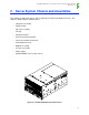
OCPRF100 MP Server System Technical Product Specification Revision 1.0 2. Server System Chassis and Assemblies This chapter describes the chassis and assembly pieces that reside within the chassis.
OCPRF100 MP Server System Technical Product Specification Revision 1.0 2.1 Front Panel Assembly The front panel assembly consists of an upper and lower bezel. The bezels serve as cosmetic pieces only, and can be integrator specific. Finger grips are provided to make it easy to remove the bezels.
OCPRF100 MP Server System Technical Product Specification Revision 1.0 Figure 2-3: Peripheral Bay 2.3 Top Cover Assembly The top cover assembly is released by removing the two retaining screws located on the top toward the front (E in Figure 2-4: Hot-plug PCI Access Door), between the fan bay assembly and the top cover assembly marked with the AC caution icon.
OCPRF100 MP Server System Technical Product Specification Revision 1.0 2.3.1 Hot-plug PCI Access Door The hot-plug PCI access door is released by removing the two retaining screws (A in Figure 2-4: Hot-plug PCI Access Door) located on the top, middle area of the server. The cover slides toward the rear of the server and lifts straight up off of the server chassis, exposing the hot-plug PCI cards.
OCPRF100 MP Server System Technical Product Specification Revision 1.0 The fan bay will operate at high speed on the following conditions: • Internal temperature has reached an elevated, but noncritical set-point. • Ambient temperate exceeds 30°C. • A fan has entered into the predictive failure mode. • A fan has failed. If the FPC detects a fan entering the predictive fan failure mode, the speed of all of the fans will be increased to maintain thermal requirements.
OCPRF100 MP Server System Technical Product Specification Revision 1.0 Fans are installed with the connector on the left side facing down. The cavities in the fan bay are keyed to prevent a fan from being installed backwards. The fan bay is installed after the Profusion carrier assembly is installed and completely seated into the midplane. The fan bay is lowered into the chassis until it is seated on the flanges of the Profusion tray.
OCPRF100 MP Server System Technical Product Specification Revision 1.0 Figure 2-6: Front Panel Board Installation 2.6 Processor Mezzanine Board The base configuration of an OCPRF100 MP server system consists of a single processor mezzanine board. The processor mezzanine board is designed to support one to four Pentium® III Xeon™ processors, providing power, ground and other connections to the processor(s) and to the Profusion carrier.
OCPRF100 MP Server System Technical Product Specification Revision 1.0 A B Captive Screw Hold-down Strap C Air Baffle Figure 2-7: Processor Retention Mechanism A processor/termination card pair is secured with a hold-down strap (B) that hooks into the back of the retention mechanism and is fastened at the front with two captive screws (A). (The retention strap is for a pair of processors or terminators). See Figure 2-7: Processor Retention Mechanism.
OCPRF100 MP Server System Technical Product Specification Revision 1.0 2.8 Profusion® Carrier Tray The processor mezzanine boards plug into the Profusion carrier tray. The Profusion carrier tray serves as a platform to provide power and signals to the processor mezzanine board, route signals through the 1008-pin grand connector, and carry components of the Profusion chip set.
OCPRF100 MP Server System Technical Product Specification Revision 1.0 then moving back into place for connection to the Profusion carrier board. Place the four lock bars over the protruding tabs and onto the Profusion carrier board (B). The release handles of the lock bars (C) should be pointed to the outside of the board and they should be in the unlocked position.
OCPRF100 MP Server System Technical Product Specification Revision 1.0 nectors begin to engage, rotate the levers back until the connectors are fully engaged. Levers should be in an upright or near upright position. Secure the tray and the processor retention mechanism to the sides of the chassis with screws (1) and (2) as indicated in Figure 2-9. 2.9 Midplane Assembly The midplane assembly serves as an interconnect between the power supplies, memory boards, Profusion carrier, and the I/O carrier.
OCPRF100 MP Server System Technical Product Specification Revision 1.0 Figure 2-11: Midplane Assembly Installed in System 2.10 I/O Carrier The I/O carrier is the interface that connects the I/O port of the Profusion chip set to the following: • Ten hot-swappable PCI slots (four of which support 66-MHz transactions). • Legacy connector (video, keyboard, serial, parallel, USB, and Intelligent Chassis Management Bus (ICMB) ports). • Dual LVDS.
OCPRF100 MP Server System Technical Product Specification Revision 1.0 Figure 2-12: I/O Carrier Tray The I/O carrier tray features tabs on the base of the tray that engage into slots on the horizontal members in the chassis. Lower the tray from the top of the system and slide the tray toward the center of the chassis using the two insert/extract handles located on the back of the tray. Secure the I/O carrier tray to the chassis with the four screws located on the sides and back of the chassis.
OCPRF100 MP Server System Technical Product Specification Revision 1.0 The PHP mechanism is a rotating part that actuates a switch located on the PHP board. There are four light emitting diodes (LEDs) per slot--two can be viewed from the rear of the system and two from inside the system. Once the LED shows which slot is powered down, the PHP mechanism can be depressed on the PHP actuator and the mechanism can be rotated out of place to remove the PCI card.
OCPRF100 MP Server System Technical Product Specification Revision 1.0 3. System Overview This chapter describes the features of the OCPRF100 MP server system chassis. System Features Table 3-1 provides a list and brief description of the features of the OCPRF100 MP server system, which utilizes the OPRF100 board set. Table 3-1: OCPRF100 MP Server System Feature List Feature Description Upgradeability The system can be upgraded to future processors within the Pentium® III Xeon™ processor family.
OCPRF100 MP Server System Technical Product Specification Revision 1.0 up to 16 GB of error correction code (ECC) PC-100 compatible registered DIMMs. The I/O carrier contains four 66-MHz and six 33-MHz 64-bit hot-swap PCI slots, I/O ports, and various controllers. Figure 3-1: OCPRF100 MP Server System Chassis with Peripheral Bay shows an isometric view of the chassis with the peripheral bay installed.
OCPRF100 MP Server System Technical Product Specification Revision 1.0 I/O Riser Board Profusion Carrier I/O Carrier Front Panel Memory Carriers Power Supplies Midplane Figure 3-2: OPRF100 Board Set/System Board Locations within Server Chassis The peripheral bay mounted at the lower front of the chassis supports a 3.5-inch floppy drive, a half-height 5.25-inch device (e.g., CD-ROM) and two 3.5-inch by 1.0- or 1.6-inch hot-swap hard drives.
OCPRF100 MP Server System Technical Product Specification Revision 1.
OCPRF100 MP Server System Technical Product Specification Revision 1.0 A B C D E F G H I J K L M N O P Q Figure 3-4: Front View of Chassis with No Bezel Table 3-2: System Features – Front Item Feature Description Front Panel Controls and Indicators A Power switch When pressed, turns the DC power inside the server on or off. B Reset switch When pressed, resets the server and causes the power-on self-test (POST) to run. C NMI switch When pressed, causes a nonmaskable interrupt (NMI).
OCPRF100 MP Server System Technical Product Specification Revision 1.0 Table 3-2: System Features – Front F Fan fault LED (yellow) When lit, indicates either a fan failure, or that a predictive fan failure has been detected in the server. G Drive fault LED (yellow) When continuously lit, indicates an asserted fault status on one or more hard disk drives in the hot-swap bay. When flashing, indicates drive rebuild in progress.
OCPRF100 MP Server System Technical Product Specification Revision 1.0 3.2.2 Rear View of Chassis A B C D E F G H I Figure 3-5: Rear View of Chassis Table 3-3: System Features – Rear Item Description A PCI add-in board slots. B External LVDS connector. C ICMB connectors in/out. D I/O riser board. E AC input power connector. F Three power supplies.
OCPRF100 MP Server System Technical Product Specification Revision 1.0 Table 3-3: System Features – Rear G PWR LED (green) – power condition – refer to Chapter Power Supply for details. H FAIL LED (yellow) – failure condition – refer to Chapter Power Supply for details. I PR_FL LED (yellow) – power supply fan predictive failure – refer to Chapter Power Supply for details. 3.2.
OCPRF100 MP Server System Technical Product Specification Revision 1.0 Table 3-4: Riser Board External I/O Connectors C. USB ports 0 (upper) and 1 (lower). D. Super VGA compatible, 15-pin video connector. E. Serial port 2 (COM2), 9-pin RS-232 connector. F. PS/2-compatible keyboard port. G. PS/2-compatible mouse port. H. ICMB port, SEMCONN* 6-pin connector. I. ICMB port, SEMCONN 6-pin connector. 3.2.4 Peripheral Bay An optional peripheral bay provides the following: • One 3.
OCPRF100 MP Server System Technical Product Specification Revision 1.0 Table 3-5: I/O External Connectors Item Bay Description A 3.5-inch bay 3.5-inch floppy drive. B 5.25-inch half-height bay 5.25-inch half-height peripheral drive. C 3.5-inch by 1.0- or 1.6-inch bays Two hot-swap capable hard drives. 3.2.5 3.5-inch User-accessible Drive Bay The system ships from the factory without the peripheral bay installed. 3.2.6 5.
OCPRF100 MP Server System Technical Product Specification Revision 1.0 3.3 Internal Chassis Features 3.3.1 Power System Three 750-W supplies in a standard configuration provide the modular power system for the system. The power system may be configured with three power supplies (2+1) for power redundancy, or with two supplies in a nonredundant configuration. The power supplies are mounted in a row at the rear bottom of the chassis. A single AC power cord provides power to the daisychained supplies.
OCPRF100 MP Server System Technical Product Specification Revision 1.0 Table 3-6: System Power Budget – Current (A) and Power (W) Profusion® Min. Load Adc 4.60 0.75 0.25 0.000 0.00 21.93 Carrier w/ Max. Load Adc 12.00 1.50 46.00 0.000 0.00 599.10 Mezzanines Max. Step Load Adc 2.00 0.75 18.00 Front Panel Min. Load Adc 0.00 0.05 2.00 0.001 0.10 24.76 Max. Load Adc 0.00 0.23 5.40 0.010 0.25 67.32 Max. Step Load Adc 0.18 0.10 0.001 0.15 Min. Load Adc 1.20 0.
OCPRF100 MP Server System Technical Product Specification Revision 1.0 Table 3-6: System Power Budget – Current (A) and Power (W) Total power (includes 2% distribution loss) Notes: 3.3.2 3.3.2.1 1. There is no 240 VA protection circuit in the OCPRF100 MP server system. 2. Minimum load for second memory carrier is zero; assumes no carrier is installed. 1268.
OCPRF100 MP Server System Technical Product Specification Revision 1.0 ies the fan input voltage. At 28°C ambient temperature, the fan input voltage is 8.0 ± 0.5 Vdc, and at 35°C, the fan input voltage is 13.5 Vdc. 3.3.2.3 Cooling Summary System Fan 70 CFM (12 Vdc Input) System Fan The system fans are sized to provide cooling for up to eight Pentium III Xeon processors.
OCPRF100 MP Server System Technical Product Specification Revision 1.0 3.3.3 3.3.3.1 PCI Hot-plug Description PCI hot plug (PHP) is the concept of removing or inserting a standard PCI adapter card from a system without stopping the software or powering down the system as a whole. “Hot Replace” means the user can replace a PCI card with an identical card. The replacement card will use the same PCI resources assigned to the previous card. OS support is required for this function.
OCPRF100 MP Server System Technical Product Specification Revision 1.
OCPRF100 MP Server System Technical Product Specification Revision 1.0 • A 240 VA protective shield on the I/O baseboard and the plastic dividers between PCI slots The LED PC board contains both the green and amber LEDs, as well as the switch that controls the PCI slot power. These items will no longer reside on the I/O carrier baseboard. This LED board is mounted in the I/O tray directly above where the PCI cards were previously screwed into the tray ledge.
OCPRF100 MP Server System Technical Product Specification Revision 1.0 Figure 3-10: PCI Card Retention Mechanism Revised non-hot plug, hot plug, and top covers are required to accommodate the additional hardware used in this enhanced solution. 3.4 Server Management The server system management architecture features several management controllers, which autonomously monitor server status and provide the interface to server management control functions.
OCPRF100 MP Server System Technical Product Specification Revision 1.0 the +5 V standby output of the power supply. The FPC takes part in implementing the following system functions: • Power and reset switch interfaces • Fan failure detection • Chassis FRU inventory • System hard reset generation • System power fault indication • ICMB bridge device • Emergency management port (EMP) • LCD interface 3.4.
OCPRF100 MP Server System Technical Product Specification Revision 1.0 • Secure mode, video blank, and floppy write protect • Front panel NMI monitoring • Software front panel NMI generation 3.4.3 Hot-swap Controller The hot-swap controller (HSC) on the LVDS SCSI hot-swap backplane is connected to other system boards via the IPMB. The HSC provides server management information through both the IPMB and the SCSI Accessed Fault-Tolerant Enclosures (SAF-TE).
OCPRF100 MP Server System Technical Product Specification Revision 1.0 3.6 Specifications 3.6.1 Environmental Specifications The system will be tested to the environmental specifications as indicated in Table 3-8. Table 3-8: Environmental Specifications Summary Environmental Feature Specification Operating temperature 10° to 35°C (50° to 95°F). See Altitude exception. Nonoperating temperature -40°C to 70°C (-40°F to 158°F). Altitude 0 to 3048 m (0 to 10000 ft.).
OCPRF100 MP Server System Technical Product Specification Revision 1.0 Table 3-8: Dimensions and Weight Specification Value Height 31.12 cm (12.25 inches, 7u) Width 44.45 cm (17.5 inches) Depth 71.12 cm (28.0 inches) Weight 51.4 kg (113 lbs.) minimum configuration 63 kg (140 lbs.) maximum configuration Required front clearance 10 inches (inlet airflow <35 °C / 95 °F) Required rear clearance 8 inches (no airflow restriction) Notes: 38 1.
OCPRF100 MP Server System Technical Product Specification Revision 1.0 4. Cables and Connectors This chapter describes cables and connectors that interconnect various components of the OCPRF100 MP server system. The block diagram in Figure 4-1: OCPRF100 Server System Interconnect Diagram shows cables that connect the boards used in the OCPRF100 MP server system.
OCPRF100 MP Server System Technical Product Specification Revision 1.0 FAN FAN FAN FAN FAN FAN 4 pin Hot-Swap LCD LCD Power Fan Connectors Front panel 14 Pin & 2 Pin CBL,PWR,AC CBL,LCD 80 Pin SCA (External Interface) Style Connector Memory Memory Carrier Carrier (16 (16 DIMMs) DIMMs) Mezzanine Profusion* Pentium(R) III Carrier Xeon(TM) or Term. 6x24x3 HDM Connector Pentium III Xeon or Term. Pentium III Xeon or Term. AC Pentium III Xeon or Term.
OCPRF100 MP Server System Technical Product Specification Revision 1.0 4.1 Cables Table 4-1 through Table 4-3 list flat ribbon cables and wire bundles that are used in the assembly of the OCPRF100 MP server system.
OCPRF100 MP Server System Technical Product Specification Revision 1.0 4.2 Connectors The following section describes the signals and pinouts for various connectors on the OPRF100 board set. 4.2.1 4.2.1.1 User-accessible I/O Connectors Keyboard and Mouse Ports These identical PS/2-compatible ports share a common housing. The top port is for the mouse and the bottom port is for the keyboard.
OCPRF100 MP Server System Technical Product Specification Revision 1.0 4.2.2 Serial Ports The I/O carrier provides two stacked RS-232C serial ports (the top one is COM1 and the bottom one is COM2). They are D-subminiature 9-pin connectors. Each serial port can be enabled separately with the configuration control provided on the I/O carrier. The COM2 serial port can be used either as an emergency management port or as a normal serial port.
OCPRF100 MP Server System Technical Product Specification Revision 1.0 4.2.3 Parallel Port The IEEE 1284-compatible parallel port—used primarily for a printer—sends data in parallel format. The parallel port is accessed through a D-subminiature 25-pin connector.
OCPRF100 MP Server System Technical Product Specification Revision 1.0 Table 4-7: Video Connector Pin Signal 1 Red (analog color signal R) 2 Green (analog color signal G) 3 Blue (analog color signal B) 4 No connection 5 GND (video ground, shield) 6–8 GND (video ground, shield) 9 No connection 10 GND (video ground) 11–12 No connection 13 HSYNC (horizontal sync) 14 VSYNC (vertical sync) 15 No connection 5 1 10 6 15 11 OM00936A Figure 4-5: Video Connector 4.2.
OCPRF100 MP Server System Technical Product Specification Revision 1.0 Table 4-8: Dual USB Connector A2 DATAL0 Differential data line paired with DATAH0. A3 DATAH0 Differential data line paired with DATAL0. A4 GND Ground potential. B1 VCC Overcurrent monitor line port 1. B2 DATAL1 Differential data line paired with DATAH1. B3 DATAH1 Differential data line paired with DATAL1. B4 GND Ground potential. A1 A4 B1 B4 Figure 4-6: Dual USB Connector 4.2.
OCPRF100 MP Server System Technical Product Specification Revision 1.0 1 6 Figure 4-7: ICMB Connector 4.2.7 Fan Connector Table 4-10: Fan Connectors (J1A1,J9A1,J10A1) 4.2.
OCPRF100 MP Server System Technical Product Specification Revision 1.0 Table 4-11: Peripheral Bay Power Connector 4.2.
OCPRF100 MP Server System Technical Product Specification Revision 1.
OCPRF100 MP Server System Technical Product Specification Revision 1.0 Table 4-12: Peripheral Bay Backplane Header (240 position) 46 +5V +5V S68 (-DB 11) GND GND 47 +5V +5V S34 (+DB 11) SDA RST_I2C_L 48 +5V +5V +5V PWR_GOOD SCL 4.2.
OCPRF100 MP Server System Technical Product Specification Revision 1.0 4.2.
OCPRF100 MP Server System Technical Product Specification Revision 1.0 Table 4-14: SCSI Connector 4.2.
OCPRF100 MP Server System Technical Product Specification Revision 1.0 Table 4-15: IDE Connectors 4.2.
OCPRF100 MP Server System Technical Product Specification Revision 1.0 5. Power Supply This document defines the requirements for a universal input switching power supply, which provides 750 watts DC with power factor corrected AC input and with current and remote sense regulation. The power supply is used with its DC outputs paralleled with other identical supplies to form a redundant power system with system operating replacement capability (hot-swap).
OCPRF100 MP Server System Technical Product Specification Revision 1.0 The power supply dimensions are 5.0" H by 5.3" W by 11.5" D. 5.1.2 Fan Requirements The power supply incorporates a 120 mm fan for self-cooling. The air comes in from the connector side, passes through the power supply, and exhausts on the fan side of the power supply. 5.2 5.2.1 Interface Requirements AC Inlet Connector The power supply has a standard IEC inlet connector. 5.2.
OCPRF100 MP Server System Technical Product Specification Revision 1.0 Notes: 1. 2. Power blades (P1 – P12) are rated at 25 A each. Signal pins (A1 – D6) are rated at 1 A each. Figure 5-2: DC Connector Drawing 5.3 Marking and Identification The power supply marking must support the following requirements: safety agency requirements, government requirements (if required, e.g., point of manufacturing), power supply vendor requirements, and Intel manufacturing and field support requirements. 5.3.
OCPRF100 MP Server System Technical Product Specification Revision 1.0 SAFETY AGENCY MARKINGS MANUFACTURER LOGO MANUFACTURER NAME MANUFACTURER MODEL NO. AND REVISION AUTORANGING INPUT: 50/60HZ INPUT 100-120V ~ 12A, OUTPUT 650W +3.3V +5V +12V 31.0A MAX 31.0A MAX 31.0A MAX -12V +5VSB +15VSB 1.0.A MAX 1.0A MAX 0.2A MAX INPUT 200-240V ~ 7A, OUTPUT 750W +3.3V +5V +12V P/N: 33.0A MAX 33.0A MAX 33.0A MAX -12V +5VSB +15VSB 1.0.A MAX 1.0A MAX 0.
OCPRF100 MP Server System Technical Product Specification Revision 1.0 5.5 Electrical Requirements 5.5.1 Efficiency The power supply has a minimum efficiency of 65% to its DC output pins at maximum load currents and at rated nominal input voltages and frequencies. The power supply has a minimum efficiency of 70% to its DC output pins at maximum load currents when the input voltage is higher than 180 Vac. 5.5.2 AC Input Voltage Specification 5.5.
OCPRF100 MP Server System Technical Product Specification Revision 1.0 tions. Protection circuits in the power supply will not cause the AC fuse to blow unless a component in the power supply has failed. This includes DC output load short conditions. The DC load short circuit protection circuits will shut down or limit power supply without causing the AC line fuse to blow. 5.5.3.3 Power Factor Correction The power supply incorporates a power factor correction circuit.
OCPRF100 MP Server System Technical Product Specification Revision 1.0 Table 5-4: Load Range Single Power Supply Load Condition Voltage Minimum Continuous Maximum Continuous +3.3 V 1.1 A 36 A +5 V 0.7 A 36 A +12 V 0.7 A 36 A -12 V 0A 1.0 A +5 V Standby 0.05 A 1.00 A +15 V Standby 0A 200 mA 5.5.4.2 Peak 42 A Remote Sense The power supply provides remote sense on the +3.3 Vdc, +5 Vdc, and +12 Vdc outputs and their common DC return to provide regulation at those remote points. 5.5.4.
OCPRF100 MP Server System Technical Product Specification Revision 1.0 5.5.4.4 Over-voltage Protection The power supply over-voltage protection is sensed locally. The power supply will shut down in a latch off mode after an over-voltage condition. The latch is cleared by toggling the power supply on signal, or by an AC power interruption of greater than 1 second but less than 10 seconds to reset from the latch off condition.
OCPRF100 MP Server System Technical Product Specification Revision 1.0 Protection. A hard short circuit should turn off the power supply immediately. A hard short circuit is defined as when the load level is less than 10 milliohms. 5.5.4.7 Current Share Requirements Equal power sharing of paralleled power supplies is required. The failure of a power supply does not affect the current sharing or output voltages of other power supplies still in operation in a redundant configuration. The +3.
OCPRF100 MP Server System Technical Product Specification Revision 1.0 Table 5-9: AC Good Signal AC OK Signal Voltage Level † Current LOW: AC is not yet up to the level. 0.4 V max 4 mA min sink current HIGH: AC is up to the level. 4 V min 0.5 mA max source current † Measured relative to the power supply DC common output ground pins 5.6.3 Power Good (Output) Each power supply provides a power good signal. A pin must be allocated for this signal.
OCPRF100 MP Server System Technical Product Specification Revision 1.0 TTL HIGH POWER GOOD SIGNAL TTL LOW Vn Vm +5VDC OUTPUT VOLTAGE t 1 (100-1500msec) Vn Vm t1 t2 t2 (1msec min.) Nominal Output Voltage +5 VDC Minimum Output Voltage +4.75 VDC Delay Turn-on (100-1500msec) Delay Turn-off(1msec min) Figure 5-5: Power Good Signal Characteristics 5.6.4 Power Supply Present Indicator (Output) This signal is used to sense the number of power supplies in the system (operational or not).
OCPRF100 MP Server System Technical Product Specification Revision 1.0 of that power supply is necessary. A “low” state indicates the power supply failure. The power supply failure signal is an output signal from the power supply to the system. Table 5-12: Power Supply Failure Power Supply Failure Signal Voltage Level † LOW STATE (power supply failure) 0.4 V max HIGH STATE (power supply OK) 4 V min † Measured relative to the power supply DC common output ground pins. 5.6.
OCPRF100 MP Server System Technical Product Specification Revision 1.0 Table 5-14: Power Supply Kill Specification Power Supply Kill Signal Voltage Level † HIGH, PWR SUPPLY IS DISABLED 4.5 V minimum LOW, PWR SUPPLY IS ENABLED 0.25 V maximum † Measured relative to the power supply DC common output ground pins. 5.6.8 Power Supply Field Replacement Unit Signals Four pins are allocated for the FRU information on the power supply connector. One pin is the Serial Clock (SCL).
OCPRF100 MP Server System Technical Product Specification Revision 1.0 Table 5-15: Power Supply LEDs and Output Signal State Logic Power Supply LEDs Power Supply Output Signal States Input to PS PRFL (yellow) FAIL (yellow) P_Good H = pwr good Pred. Failure H = pred.
OCPRF100 MP Server System Technical Product Specification Revision 1.0 6.
OCPRF100 MP Server System Technical Product Specification Revision 1.0 entered by pressing F2 during POST. BIOS Setup is further described in Section BIOS Setup Utility.1 The iFLASH utility updates the system flash ROM. It provides security features that reduce the risk of tampering. A recovery boot block allows recovery from catastrophic problems. The recovery boot block is electrically protected from erasure by a jumper on the OPRF100 I/O carrier. 6.
OCPRF100 MP Server System Technical Product Specification Revision 1.0 If the boot strap processor (BSP) fails during POST, BIOS will attempt to boot the system using another processor. This feature is called fault resilient booting (FRB). For additional information on FRB, see the OPRF100 MP Board Set Technical Product Specification. 6.1.2 Profusion® Chip Set The Profusion PCIset connects the processors, memory, and four peer PCI buses.
OCPRF100 MP Server System Technical Product Specification Revision 1.0 Ultra I/O chip also provides a keyboard controller containing Phoenix* microcode. BIOS downloads commands to the keyboard controller to provide various security features. The I/O carrier contains 10 hot-plug PCI slots plus a PCI SVGA controller (Cirrus Logic* CLGD5446) and a dual-channel low-voltage differential SCSI controller (Symbios* SYM53C896). The flash ROM contains the option ROM (OPROM) for both of these components.
OCPRF100 MP Server System Technical Product Specification Revision 1.0 The system supports the S1, S4 OS, and S5 sleep states. It also supports Wake-on-LAN* from the S1 and S4 states. After the operating system sends the command to switch to ACPI mode, the power button acts as a sleep button and a power button. If the button is pressed for less than four seconds, the system enters a sleep state determined by the operating system.
OCPRF100 MP Server System Technical Product Specification Revision 1.0 the system BIOS provides the run-time functions necessary to boot from an I2O mass-storage adapter card. I2O devices are added to the interrupt 13h chain and booted using these calls. 6.2.3 Management Management of clients and servers is a major issue for end users. The system BIOS supports server management applications through the following specifications: • Desktop Management Interface (DMI) Specification, Version 2.
OCPRF100 MP Server System Technical Product Specification Revision 1.0 6.3 BIOS Setup Utility The OCPRF100 MP server system BIOS automatically configures system resources. BIOS Setup allows the user to set preferences about system operation. It stores these preferences in CMOS configuration RAM. Because BIOS Setup resides in flash ROM, the user can invoke it without booting an operating system.
OCPRF100 MP Server System Technical Product Specification Revision 1.0 Table 6-2. BIOS Setup Keyboard Commands ESC Exit The Escape key allows the user to back out of any field. When the Escape key is pressed while editing a field, the edit of that field is terminated. When the Escape key is pressed in a submenu, the parent menu is re-entered. When it is pressed in a top-level menu, the Exit Menu appears. ¦ Select Item The up arrow selects the previous value in an option list.
OCPRF100 MP Server System Technical Product Specification Revision 1.0 Table 6-3: Main Menu Legacy Diskette B: Disabled† 360KB, 5 ¼” 1.2 MB, 5 ¼” 720KB, 3 ½” 1.44/1.25 MB, 3 ½” 2.88 MB, 3 ½” Selects the floppy diskette type for drive B. Primary Master Selects IDE submenu. Primary Slave Selects IDE submenu. Processor Information Selects Processor Information submenu. Keyboard Features Selects Keyboard Features submenu.
OCPRF100 MP Server System Technical Product Specification Revision 1.0 Table 6-4. IDE Submenu LBA Mode Control Disabled Enabled Displays status of Logical Block Access. Autotyped by BIOS. 32 Bit I/O Disabled† Enabled Enables 32-bit IDE data transfers. Transfer Mode Standard Fast PIO 1 Fast PIO 2 Fast PIO 3 Fast PIO 4 Selects the method for transferring data to/from the drive. Autotyped by BIOS.
OCPRF100 MP Server System Technical Product Specification Revision 1.0 Table 6-6: Keyboard Features Submenu Feature Option Description Numlock Auto† On Off Selects the power-on state of the Num Lock key. Key click Disabled† Enabled Enables key click. Keyboard auto-repeat rate 30/sec† 26.7/sec 21.8/sec 18.5/sec 13.3/sec 10/sec 6/sec 2/sec Selects key repeat rate. Keyboard auto-repeat delay ¼ sec ½ sec† ¾ sec 1 sec Selects delay before key repeat.
OCPRF100 MP Server System Technical Product Specification Revision 1.0 Table 6-7: Advanced Menu Pause Before Boot Disabled Enabled† If enabled, BIOS pauses for five seconds before booting the operating system. PCI Configuration Selects PCI Configuration submenu. I/O Device Configuration Selects I/O Device Configuration submenu. Advanced Chip Set Control Selects Advanced Chip Set Control submenu. NOTES: Default values are marked with the "†" symbol.
OCPRF100 MP Server System Technical Product Specification Revision 1.0 Table 6-9: PCI Mode Submenu Feature Option Description Option ROM Scan Disabled Enabled† Enables option ROM scan. Enable Master Disabled Enabled† Enables device(s) as a PCI bus master. Latency Timer Default 0020h 0040h 0060h 0080h† 00A0h 00C0h 00E0h Specifies the minimum guaranteed number of PCI bus clocks that a device can master on a PCI bus during one transaction. NOTES: Default values are marked with the "†" symbol.
OCPRF100 MP Server System Technical Product Specification Revision 1.0 Table 6-10: I/O Device Configuration Submenu Mode Output only Bidirectional† EPP ECP Selects the mode of the LPT port. Base I/O Address 378h† 278h 178h 3BCh Selects the base I/O address for LPT port. 178h is only available when the LPT port is in EPP mode. Otherwise, 3BCh is available. Interrupt IRQ 5 IRQ 7† Selects the IRQ for LPT port.
OCPRF100 MP Server System Technical Product Specification Revision 1.0 6.3.3 Security Menu Table 6-12: Security Menu describes the Security Menu. Table 6-12: Security Menu Feature Option Description User Password is Set Clear† Status only. Administrator password must be enabled before user password can be enabled. User password is enabled by entering a user password and disabled by entering a null user password. Administrator Password is Set Clear† Status only.
OCPRF100 MP Server System Technical Product Specification Revision 1.0 6.3.4 Server Menu Table 6-13: Server Menu through Table 6-16: Console Redirection Submenu describe the Server Menu and submenus. Table 6-13: Server Menu Feature Option Description System Management Selects System Management submenu. Console Redirection Selects Console Redirection submenu. Processor Retest No† Yes Select “Yes” to clear historical processor status and retest all processors on the next boot.
OCPRF100 MP Server System Technical Product Specification Revision 1.0 Table 6-14: System Management Submenu Clear Event Log Disabled† Enabled Clears the system event log. This option is reset to disabled on each boot. Memory Scrubbing Disabled Enabled† Enables memory scrubbing by the Profusion® chip set. AERR Enable Disabled Enabled† Enables AERR to be asserted on the processor host buses. Assert NMI on BERR Disabled Enabled† Enables BERR to be reported as a critical event via NMI. .
OCPRF100 MP Server System Technical Product Specification Revision 1.0 Table 6-16: Console Redirection Submenu Feature Option ?Description COM Port Address Disabled† 3F8 2F8 3E8 When enabled, use the I/O port specified. IRQ # 3† 4 When enabled, use the IRQ specified. COM Port Baud Rate 9600† 19.2KB 38.4KB 115.2KB When enabled, use the baud rate specified. The maximum baud rate supported by the Emergency Management Port is 19.2K.
OCPRF100 MP Server System Technical Product Specification Revision 1.0 Table 6-17: Boot Menu Message Timeout Multiplier 1† 2 4 8 10 50 100 1000 All I2O message timeout values are multiplied by this number. Pause During POST Disabled† Enabled Use this to start the IRTOS (I2O Real Time Operating System) manually. When POST has stopped, it issues three beeps. Pressing any key continues POST. NOTES: Default values are marked with the "†" symbol. 6.3.6 Exit Menu Table 6-18 describes the Exit Menu.
OCPRF100 MP Server System Technical Product Specification Revision 1.0 • System BIOS • Embedded video BIOS and SCSI BIOS • BIOS Setup Utility • Integrator-supplied user binary area • Language file iFLASH communicates with the existing BIOS to provide security mechanisms which reduce the risk of tampering. It also communicates with BIOS to verify that the new BIOS image is compatible with the existing image. This helps to prevent an incorrect BIOS from being placed into flash memory.
OCPRF100 MP Server System Technical Product Specification Revision 1.0 7. Regulatory Specifications The OCPRF100 MP server system, utilizing the OPRF100 board set, meets the specifications and regulations for safety and EMC as defined in this chapter. 7.1 7.2 7.3 Safety Compliance USA/Canada: UL 1950, 3rd Edition/CSA 22.2, No.
OCPRF100 MP Server System Technical Product Specification Revision 1.0 7.4 Electromagnetic Compatibility Notice (USA) This equipment has been tested and found to comply with the limits for a Class A digital device, pursuant to part 15 of the FCC Rules. These limits are designed to provide reasonable protection against harmful interference when the equipment is operated in a commercial environment.
OCPRF100 MP Server System Technical Product Specification Revision 1.0 8. Peripheral Bay Backplane Board This chapter describes the features and functionality of the peripheral bay backplane board, which is also referred to as the backplane. The backplane is designed in compliance with the SCSI Command Set For Enclosure Services Document Specification, and SCSI Accessed FaultTolerant Enclosures Interface Specification.
OCPRF100 MP Server System Technical Product Specification Revision 1.0 8.1.1 Architectural Overview The backplane is an integral part of the OCPRF100 MP Server System. It is designed to provide a cost effective ease of power-on (hot-swap) drive replacement, provide easy RAID integration over a wide range of RAID controller products, and be vendor independent.
OCPRF100 MP Server System Technical Product Specification Revision 1.0 Drive Fault Indication Support Public I2C BUS LVD/SE Active Terminators Power Control CPU Unit SCA2 Connectors SCSI Interface with LVD/SE switch Narrow SCSI Connector Serial EEPROM Private I2C Temperature Sensor Floppy Connector LVDS SCSI Connector to Host Controller IDE Connector Figure 8-2: Functional Block Diagram 8.2.
OCPRF100 MP Server System Technical Product Specification Revision 1.0 ² Spin-down of a drive when failure is detected and reported (using enclosure services messages) via the SCSI bus. An application or RAID controller detects a drive-related problem that indicates a data risk. In response, it takes the drive out of service and sends a spin down SCSI command to the drive. This decreases the likelihood that the drive is damaged during removal from the hot-swap drive bay.
OCPRF100 MP Server System Technical Product Specification Revision 1.0 8.2.7.3 Fault LEDs The hot-swap controller is responsible for turning the drive fault LEDs on or off according to the states specified via commands received through SAF-TE and the IPMB. The drive fault LEDs are yellow and serve to indicate failure status for each drive. The LEDs are physically located on the LVDS SCSI backplane, and are driven from the backplane.
OCPRF100 MP Server System Technical Product Specification Revision 1.0 supply. The second is the output from an onboard Dallas DS1233* reset controller, in which RST is kept active for approximately 350 ms after the power supply has reached the selected tolerance. These two signals are ORed to keep the board in reset.
OCPRF100 MP Server System Technical Product Specification Revision 1.0 Since the standard 80C51 onchip functions are the same on the 80C652, the SFR locations, bit locations, and operation are unchanged. The only exception is in the interrupt enable and interrupt priority SFRs. These have been changed to include the interrupt from the I2C serial port. 8.3.2.4 I2C Serial Communication-SI01 The I2C pins are alternate functions to port pins P1.6 and P1.7. Because of this, P1.6 and P1.
OCPRF100 MP Server System Technical Product Specification Revision 1.0 Noise margin minimum on the high level is 0.2 VDD. 8.3.3 SCSI Controller The SCSI controller selected for this backplane is an 8-bit SYM53C80S controller. Device selection is memory mapped at address FB00-FC00. It is reset on power up and when reset is asserted to the backplane. SYM53C80S access slows down the bus; it is recommended to pulse SAF-TE infrequently. SAF_TE command processing is 2–10 ms.
OCPRF100 MP Server System Technical Product Specification Revision 1.0 Standby (Disable Mode) 5µA 3 pF channel capacitance 8.4.2 Single Ended Termination The following is a list of the features of the single-ended SCSI termination. • Fully compliant with SCSI, SCSI-2, and SCSI-3 standards. • Backward compatible to the DS2107* and DS2107A*. • Provides active termination for nine signal lines. • Laser-trimmed 110 ohm termination resistors have 2% tolerance. • Low dropout voltage regulator.
OCPRF100 MP Server System Technical Product Specification Revision 1.0 A description of each memory block is provided, showing the purpose and function as determined by microcontroller programming. These functions may also be controlled by system software using SCSI commands defined in the SAF-TE specification. Figure 8-4: Microcontroller Memory Map 8.6.1.1 Flash Memory Region (0x0000 – 0x7FFF) The Atmel* 27C257 or equivalent Flash EPROM is accessible as either a data or program memory read.
OCPRF100 MP Server System Technical Product Specification Revision 1.0 each region is a single address. Thus, aliases will occur on byte boundaries throughout the remainder of the region decoded for that function. Note that the eighth region from 0xFF00 – 0xFFFF is not used. In register bit descriptions listed below, five fields are shown: the data bit number(s), the name of the field, how the bit(s) respond to a reset, whether the bits are readable and/or writeable, and a description of the field.
OCPRF100 MP Server System Technical Product Specification Revision 1.0 8.6.1.3.3 Drive Present Status Region (0xFA00 – 0xFAFF) The absence or presence of each drive is detected by the state of pin 44 on that drive’s SCA connector. A drive that is present will have its corresponding bit set to one in this register. Bits 7:6 in this register indicate the revision of the PLD code that is installed.
OCPRF100 MP Server System Technical Product Specification Revision 1.0 Table 8-4: P1 Functions Bit Name I/O Fixed† Function 7 SDA I/O Y I2C serial data signal for the IPMB. 6 SCL I/O Y I2C serial clock signal for the IPMB. 5 Reserved - N Reserved for future use. 4 SCSI _reset_L O N Reset SCSI controller. If 0, places the 53C80S SCSI chip into reset. If 1, the SCSI interface chip comes out of reset and operates normally. 3 SCSI_DRQ I N SCSI DMA Request.
OCPRF100 MP Server System Technical Product Specification Revision 1.0 Table 8-5: P3 Functions 6 WR_L O Y Write strobe. Indication from the microcontroller that the current bus cycle is a write operation. 5 Reserved - N Reserved for future use. 4 Reserved - N Reserved for future use. 3 INT1_L I Y Interrupt 1. Connected to the SCSI bus reset signal RST_L. 2 INT0_L I Y Interrupt 0. Connected to the 53C80S* SCSI chip interrupt. 1 Reserved - N Reserved for future use.
OCPRF100 MP Server System Technical Product Specification Revision 1.0 8.7.5 CONN_MODE This becomes the TMS input on the JTAG ports of all the PLDs. TMS is a mode select pin which controls the function of the JTAG port. If the enable signal is high (i.e., disabled), the mode signal is degated from the TMS pin, and TMS is held high, which keeps the JTAG port in an idle state. 8.7.6 CONN_SCLK This is connected to the TCK clock input on the JTAG port of all the PLDs. 8.
OCPRF100 MP Server System Technical Product Specification Revision 1.
OCPRF100 MP Server System Technical Product Specification Revision 1.
OCPRF100 MP Server System Technical Product Specification Revision 1.0 Table 8-6: Floppy Disk Connector 9 GND 10 FD_MTR0_L 11 GND 12 FD_DR1_L 13 GND 14 FD_DR0_L 15 GND 16 FD_MTR1_L 17 FD_MSEN1 18 FD_DIR_L 19 GND 20 FD_STEP_L 21 GND 22 FD_WDATA_L 23 GND 24 FD_WGATE_L 25 GND 26 FD_TRK0_L 27 FD_MSEN0 28 FD_WPROT_L 29 GND 30 FD_RDATA_L 31 GND 32 FD_HDSEL_L 33 GND 34 FD_DSKCHG_L 8.8.1.
OCPRF100 MP Server System Technical Product Specification Revision 1.
OCPRF100 MP Server System Technical Product Specification Revision 1.0 Table 8-8: BERG* 240-Pin Right Angle 5 X 48 Connector Pinout 41 +5v +5v S7 (+DB 1) S42 (-DB 2) S9 (+DB 3) 42 +5v +5v S38 (-DB 15) S5 (+DB P1) S40 (-DB 0) 43 +5v +5v S4 (+DB 15) S39 (-DB P1) S6 (+DB 0) 44 +5v +5v S35 (-DB 12) S2 (+DB 13) S37 (-DB 14) 45 +5v +5v S1 (+DB 12) S36 (-DB 13) S3 (+DB 14) 46 +5v +5v GND GND GND 47 +5v +5v GND SDA Reserved 48 +5v +5v GND PWR_GOOD SCL 8.8.1.
OCPRF100 MP Server System Technical Product Specification Revision 1.0 Table 8-9: IDE Connector 35 DA0 36 DA2 37 CS1P_L 38 DS3P_L 39 DHACT_L 40 GROUND 8.8.1.
OCPRF100 MP Server System Technical Product Specification Revision 1.0 9. Peripheral Bay Board (Chassis Side) This chapter describes the design of the peripheral bay board (chassis side). This board, used in the OCPRF100 MP server system, is attached to the OCPRF100 MP server system chassis and provides power and signal distribution to the peripheral bay backplane and other system peripheral devices.
OCPRF100 MP Server System Technical Product Specification Revision 1.0 1.) 89009-149 (BERG*) Blind Mate Connector Header 2.) 73475-101 (BERG) Guide Pin Housing 3.) 70295-001 (BERG) Guide Pin and Screw 4.) 20-position power Connector 5.) 34-position Header (floppy) 6.) 40-position Header IDE 7.) Wide SCSI Connector 8.
OCPRF100 MP Server System Technical Product Specification Revision 1.0 10. Front Panel This chapter describes the design and external interface of the OCPRF100 MP server system front panel. The front panel provides a user interface to the OCPRF100 MP server system via push buttons, indicator LEDs, an LCD panel, and a speaker. It also provides an interface to external systems via the ICMB. All of the front panel functions are controlled by a Philips* 80C652 microcontroller.
OCPRF100 MP Server System Technical Product Specification Revision 1.0 All of the front panel’s functions are controlled by a Philips 80C652 microcontroller and are available at all times when AC power is available. The connection from the front panel to the rest of the OCPRF100 MP server system is via the 80-pin connector to the OCPRF100 Profusion carrier. All six system fans plug into the OCPRF100 MP server system front panel.
OCPRF100 MP Server System Technical Product Specification Revision 1.0 10.2.2.
OCPRF100 MP Server System Technical Product Specification Revision 1.
OCPRF100 MP Server System Technical Product Specification Revision 1.
OCPRF100 MP Server System Technical Product Specification Revision 1.
OCPRF100 MP Server System Technical Product Specification Revision 1.0 10.2.3.3 UART A universal asynchronous receiver/transmitter (UART) is memory mapped to the microcontroller’s bus to allow concurrent operation of the ICMB and EMP ports. The UART is used for the EMP interface. 10.2.3.4 Serial EEPROM/Temperature Sensor The serial EEPROM is accessible on the FPC’s private I2C bus.
OCPRF100 MP Server System Technical Product Specification Revision 1.0 Table 10-5: FRU Information lists the board specific FRU information that is programmed into the board information area. Table 10-5: FRU Information Board Information Information Description Example Notes Manufacturing date/ time Time and date of board manufacture (value programmed [in hex] is the number of minutes after 0:00 hrs 1/1/ 96). (Date/time translation shown below.) f593h = 62867 min. Manufacturer Board manufacturer.
OCPRF100 MP Server System Technical Product Specification Revision 1.
OCPRF100 MP Server System Technical Product Specification Revision 1.0 10.2.3.5 System Event Log (SEL) The system event log (SEL) serial EEPROM (which resides on the OCPROF100 I/O carrier on the BMC’s private I2C bus) can be accessed by the front panel’s private bus under certain conditions. This feature has been added to allow access when main power is down.
OCPRF100 MP Server System Technical Product Specification Revision 1.0 10.2.5 Front Panel LCD The front panel LCD is a Stanley GMD1620A*. The LCD and the LCD’s LED backlighting unit are powered off of the main +5 V. Therefore, this capability is only available when the +5 V power is available. In order to avoid loss of 5 V standby power and LCD latch-up, the firmware must comply with the following. When main power is OFF, all signals driving the LCD should be disabled or driven low.
OCPRF100 MP Server System Technical Product Specification Revision 1.0 All four latches may be read by the microcontroller. Reading by the microcontroller causes the latch to be deasserted (assuming that the asserting signal is also deasserted). With this interrupting scheme, it is suggested that the FPC use the power interrupt in level mode, not edge mode. This is because a reassertion of an interrupting source at the wrong time could prevent the interrupt pin from being toggled. 10.2.6.
OCPRF100 MP Server System Technical Product Specification Revision 1.0 10.2.7.1 Resetting the System The FPC has the capability to reset the entire system (processors, chip sets, etc.) by asserting the HARD_RESET signal. It must be asserted for a minimum of 500 ms. There is no maximum. 10.2.7.2 Reset Inputs The state of the reset switch can be determined by reading the RST_SWT_LATCH signal within the PLD.
OCPRF100 MP Server System Technical Product Specification Revision 1.0 10.2.7.6 Development and Test Reset In development and board testing the PLD and microcontroller can be put into a reset state by asserting the PB_RST_L signal. 10.2.8 Speaker The front panel contains a speaker that is controlled by either the FPC or the I/O board. The speaker is energized if either source commands the speaker on. The speaker impedance is approximately 8 ohms.
OCPRF100 MP Server System Technical Product Specification Revision 1.0 10.2.10.2 Receive Forced Switching In certain cases it is desirable to force a specific RXD (COM2 or ICMB) into the FPC’s RXD input. This section covers this forced switch capability. To force the ICMB’s RXD signal into the FPC’s RXD input, assert the FORCE_RXD_ICMB_LATCH and deassert the FORCE_RXD_COM2_LATCH. To force the COM2’s RXD signal into the FPC’s RXD input, assert the FORCE_RXD_COM2_LATCH and deassert the FORCE_RXD_ICMB_LATCH.
OCPRF100 MP Server System Technical Product Specification Revision 1.0 10.2.10.5 ICMB Transmit Control The FPC’s TXD (transmitted) pin drives both the COM2’s SOUT_TTL_COM2 signal and the ICMB’s SOUT_TTL_ICMB signal. There is no interlock for preventing the FPC from simultaneously transmitting on both ICMB and COM2; in fact, this capability could be desirable. The FPC drives the ICMB bus with the FPC’s TXD output whenever the ICMB_EN_LATCH is asserted (high). 10.2.10.
OCPRF100 MP Server System Technical Product Specification Revision 1.0 To switch between the SMC and FPC connection of COM2, both signals should be deasserted before either signal is asserted. When main power is off, the COM2_TO_SIO_EN signal should never be asserted. 10.2.10.7 Transmit and SMC/Front Panel Connection Control The FPC’s interrupt 2 input is logically the same signal as the signal connected to the FPC’s RXD pin. The description in this section, therefore, applies to both signals.
OCPRF100 MP Server System Technical Product Specification Revision 1.0 Table 10-8: Debounce Characteristics and Requirements Potential Switch Cycle characteristics (Press to Release) [no firmware requirements derived from this row] 0 200 Infinity † Note that although the keypad press-release cycle may be as short as zero, worst case, the firmware is only required to detect a cycle as short as 50 ms. 10.2.11.
OCPRF100 MP Server System Technical Product Specification Revision 1.
OCPRF100 MP Server System Technical Product Specification Revision 1.0 cifically, this bus connects the FPC and BMC. Also, there may be an SMM based device on the bus and a cluster card connector based device. On the FPC, this bus consists of the I2C_BACKUP_SCL and the I2C_BACKUP_SDA signals. 10.2.12.3 I2C Development Support Jumpers Development support jumpers on the I2C buses are provided to isolate I2C devices.
OCPRF100 MP Server System Technical Product Specification Revision 1.0 Appendix A: Glossary This appendix contains important terms used in the preceding chapters.
OCPRF100 MP Server System Technical Product Specification Revision 1.0 FRU Field replaceable unit GB Gigabyte.
OCPRF100 MP Server System Technical Product Specification Revision 1.
OCPRF100 MP Server System Technical Product Specification Revision 1.
OCPRF100 MP Server System Technical Product Specification Revision 1.0 Appendix B: References The following documents further describe the OCPRF100 MP Server System: • Saber System External Architecture Specification, Intel Corporation, OR-1300. • OCPRF100 MP Server System BIOS External Architecture Specification, Revision 2.0, Intel Corporation, OR-1522. • System Setup Utility External Product Specification, Intel Corporation, OR-1510.
OCPRF100 MP Server System Technical Product Specification Revision 1.0 • PCI Hot-plug (PHP) Usage Model Whitepaper, version 0.55. • Intelligent I/O (I2O) Architecture Specification, Revision 1.0, I2O Special Interest Group. I2O MPS • MultiProcessor Specification, Versions 1.1 and 1.4, Intel Corporation. PC-100 • PC SDRAM Registered DIMM Specification, Revision 1.0, February 1998, Intel Corporation, http://developer.intel.com/design/pcisets/memory/index.
OCPRF100 MP Server System Technical Product Specification Revision 1.0 PID • Programmable Interrupt Device External Product Specification, Revision 1.1, Intel Corporation, Number OR4-680777. PIIX4 • 82371AB PCI-TO-ISA/IDE Xcelerator (PIIX4) Datasheet, April 1997, Intel Corporation, Number 290562-001, ftp://download.intel.com/design/pcisets/datashts/29056201.pdf. • Intel 82371AB (PIIX4) Specification Update, December 1997, Intel Corporation, Number 297738-002, ftp://download.intel.
OCPRF100 MP Server System Technical Product Specification Revision 1.0 • USB • VGA • • FDC37C93xAPM Advance Information, 15 July 1996, Standard Microsystems Corporation.* Universal Serial Bus Specification, Revision 1.0, 15 January 1996, http://www.usb.org/ developers. CL-GD5446 Advance Product Bulletin, Cirrus Logic.* Alpine VGA Family - CL-GD543x/4x Technical Reference Manual, February 1995, Cirrus Logic. Wired for Management • Wired for Management Baseline Specification, Version 1.
OCPRF100 MP Server System Technical Product Specification Revision 1.
OCPRF100 MP Server System Technical Product Specification Revision 1.