NuPRO-850 Full-Size ePCI-X System Host Board Intel® Pentium® 4 processor User’s Manual Recycled Paper
© Copyright 2004 ADLINK Technology Inc. All Rights Reserved. Manual Rev. 1.00: June 18, 2004 Part Number: 50-13045-100 The information in this document is subject to change without prior notice in order to improve reliability, design, and function and does not represent a commitment on the part of the manufacturer.
Getting Service from ADLINK Customer Satisfaction is top priority for ADLINK Technology Inc. If you need any help or service, please contact us. ADLINK TECHNOLOGY INC. Web Site http://www.adlinktech.com Sales & Service Service@adlinktech.com TEL +886-2-82265877 Address 9F, No. 166, Jian Yi Road, Chungho City, Taipei, 235 Taiwan FAX +886-2-82265717 Please email or FAX your detailed information for prompt, satisfactory, and consistent service.
Table of Contents Chapter 1 Introduction.................................................................. 1 1.1 1.2 1.3 1.4 Unpacking Checklist........................................................................ 2 Features .......................................................................................... 3 Functional Blocks and Main Board .................................................. 4 Specifications ..................................................................................
How to Use This Guide This manual is designed to help users configure the NuPRO-850 Full-Size ePCI-X System Host Board with Dual Xeon CPU. It is divided into five chapters. Chapter 1 Introduction Gives an overview of the product features, applications, and specifications. Chapter 2 Connectors and Jumpers Outlines all the connectors and its pin definitions. Chapter 3 Getting Started Summarization of what is required to setup an operational system using the NuPRO-850.
1 Introduction The NuPRO-850 is a full-size ePCI-X System Host Board (SHB) based on the Intel® Pentium® 4 processor and 875P Memory Controller Hub / 6300ESB I/O Controller Hub chipset. It features AGP4X/8X VGA, Serial ATA I/F, Gigabit Ethernet, and USB v2.0 I/F. It supports two PCI/PCI-X busses via the Intel 6300ESB chipset (one PCI-X 64-bit/66MHz bus and one PCI 32-bit/33MHz bus).
1.1 Unpacking Checklist Check the shipping carton for any damage. If the shipping carton and contents are damaged, notify the dealer for a replacement. Retain the shipping carton and packing materials for inspection by the dealer. Obtain authorization before returning any product to ADLINK. Check the following items are included in the package, if there are any items missing, contact your dealer. • The NuPRO-850 module (May be equipped with different speed or capacity CPU, RAM, and HDD).
1.2 Features • PICMG 1.2 Rev 1.0 Embedded PCI-X Specification compliant. • PCI Local Bus Specification, Rev 2.2 compliant. • Single Intel® Pentium® 4 processor with 1MB L2 cache, 533/800MHz FSB, Hyper-Threading Technology. • Four 184-pin DIMM sockets, support single/dual channel DDR DIMM. Up to four DIMMs of DDR 266/333/400 with ECC unbuffered. Supports a maximum of 4GB of system memory. • Intel® 82547GI Gigabit Ethernet Controller. Supports 1000Base-TX, 100Base-TX and 10Base-T (IEEE802.3, 802.
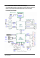
1.3 Functional Blocks and Main Board The following topics provide an overview of the NuPRO-850 main features as shown in the functional block diagram below and also the main board.
Main Board Drawing P M A B 8 7 4 A G P m Figure 2: Main Board Drawing Introduction • 5
1.3.1 Intel® Pentium® 4 Processor The Intel® Pentium® 4 processor is based on Intel® NetBurst® microarchitecture and built with Intel®'s 0.13-micron and 90nm manufacturing process and featuring Hyper-Threading technology, a 1MB level two-cache size. The Intel® Pentium® 4 has a maximum clock speed of 3.4GHz and front side bus frequency of 400/533/800MHz.
1.3.7 Software The NuPRO-850 is compatible with all major PC operating systems. ADLINK provides support, which may include additional drivers for ADLINK peripherals. Software device drivers for the NuPRO-850 may be found in the ADLINK CD. 1.3.8 AC’97 Link NuPRO-850 provides one AC’97 link 10-pin header, the AC’97 link is provided by the 6300ESB ICH. 1.3.9 Serial I/O NuPRO-850 provides one RS-232 serial port via one 10-pin connector.
1.4 Specifications Compliant Specifications • PICMG 1.2 Rev 1.0 Embedded PCI-X Specification compliant. • PCI Local Bus Specification, Rev 2.2 compliant. Form Factor • Standard Full-Size ePCI-X System Host Board, 338.6mm x 122mm (13.33”x4.8”). CPU/Cache • Intel® Pentium® 4 processor. The socket supports CPUs manufactured using Intel's 0.13-micron and 90nm manufacturing processes, FC-mPGA4 package (478-pin). • The Intel Pentium® 4 processor runs at a core speed of up to 3.
DDR DIMM timing register, which provides the DIMM speed control for the entire array, must be programmed to use the timings of the slowest DIMMs installed. Note: DIMMs must be populated in identical pairs for dual-channel operation BIOS: Award / Phoenix BIOS advanced by ADLINK • NuPRO-850 supports BIOS memory size up to 8Mbytes (Firmware Hub I/F). • Flash write protection will be implemented under software control. This bit must be set to 1 before any write will be allowed to the BIOS Flash.
• The NuPRO-850 edge connector uses three standard 32-bit PCI connectors. These three connectors carry two busses, one PCI-X 64-bit/66MHz bus and one PCI 32-bit/33MHz bus. Both busses are provided by Intel 6300ESB ICH. Hardware Monitor • The W83L784R provides temperature, fans, and voltage monitors. It has analog to digital converters that allow software to monitor the voltages on NuPRO-850. OS Compatibility • MS-DOS 6.2+, Windows 2000/XP, Red Hat Linux 7.
2 Jumpers and Connectors This chapter will familiarize the user with the NuPRO-850 with the interfaces and connections available before getting started.
2.1 2.1.
2.1.
Table 1: Description of Connector Locations 2.2 NuPRO-850 Connector Pin Assignments A detailed description and pin-out for each connector is given in the following section. 2.2.1 VGA CRT connector (CN13) PIN 1 2 3 4 5 6 7 8 9 10 11 12 SIGNAL RED GREEN BLUE NC GND GND GND GND 5VCC GND NC DDC_DATA 13 HSYNC 14 VSYNC 15 DDC_CLK Table 2: VGA Connector Pin Definition 2.2.2 USB 2.
2.2.3 Gigabit Ethernet connector (LAN1) Green / Orange LED PIN 1 2 3 4 5 6 7 8 SIGNAL MDI[0]+ MDI[0]MDI[1]+ MDI[1]MDI[2]+ MDI[2]MDI[3]+ MDI[3]- Yellow LED Table 4: Gigabit Ethernet Connector Pin Definition LED Color Green / Orange (Speed status) Yellow (Link status) Status Orange Green ON OFF Blinking Function 1000Mbps 100Mbps Link No link Data transfer in progress Table 5: Ethernet Color LED Status 2.2.
2.2.5 AC’97 connector (CN6) PIN 1 2 3 4 5 6 7 8 9 10 SIGNAL GND GND 5VCC 5VCC AC_SYNC AC_BITCLK AC_SDIN0 AC_SDOUT AC_SDIN1 AC_RST# FUNCTION Ground Ground +5V +5V AC’97 Sync AC’97 Bit Clock AC’97 Serial Data In 0 AC’97 Serial Data Out AC’97 Serial Data In 1 AC’97 Reset Table 7: AC’97 connector (CN6) 2.2.6 Case Open connector (CN1) Signal is connected to a limit switch sensor of the chassis to detect if the case is open or closed.
2.2.7 VGA 2nd CRT pin header (CN12) 8 1 10 7 PIN 1 2 3 4 5 6 SIGNAL CRT2_DATA CRT2_CLK CRT2_RED CRT2_GREEN CRT2_BLUE CRT2_HSYNC 7 CRT2_VSYNC 8 9 10 11 12 13 14 VCC_CRT2 NC GND GND GND GND GND FUNCTION DDC Data for CRT2 DDC Clock for CRT2 CRT2 Analog RED CRT2 Analog GREEN CRT2 Analog BLUE CRTR2 Horizontal sync for Monitor CRT2 Vertical sync for Monitor +5V No Connect Ground Ground Ground Ground Ground Table 9: VGA 2nd CRT pin header (CN12) 2.2.
2.2.
2.2.11 ATX 12V 4-pin connector (PN1) 3 1 4 2 PIN 1 2 3 4 SIGNAL GND GND ATX12V ATX12V FUNCTION Ground Ground +12V +12V Table 12: Floppy Connector Pin Definition 2.2.
2.2.
2.2.
2.2.15 Mini PCI Socket (CN9) PIN SIGNAL 1 3 5 7 9 11 13 15 17 19 21 23 25 27 29 31 33 35 37 39 41 43 45 47 49 51 53 55 57 59 61 NC NC NC NC NC NC NC GND INTB# +3.3V EX_CLK GND CLK GND REQ# +3.3V AD[31] AD[29] GND AD[27] AD[25] EX_IDSEL# C/BE[3] AD[23] GND AD[21] AD[19] GND AD[17] C/BE[2] IRDY# 22 • Jumpers and Connectors PIN 2 4 6 8 10 12 14 16 18 20 22 24 26 28 30 32 34 36 38 40 42 44 46 48 50 52 54 56 58 60 62 SIGNAL NC NC NC NC NC NC NC EX_INTC# +5V INTA# EX_INTD# +3.3VS RESET# +3.
63 65 67 69 71 73 75 77 79 81 83 85 87 89 91 93 95 97 99 101 103 105 107 109 111 113 115 117 119 121 123 +3.3V CLKRUN# SERR# GND PERR# C/BE[1] AD[14] GND AD[12] AD[10] GND AD[8] AD[7] +3.3V AD[5] EX_GNT# AD[3] +5V AD[1] GND AC_SYNC AC_SDIN AC_BITCLK AC_ID1# NC NC NC NC NC NC +5Analog 64 66 68 70 72 74 76 78 80 82 84 86 88 90 92 94 96 98 100 102 104 106 108 110 112 114 116 118 120 122 124 FRAME# TRDY# STOP# +3.3V DEVSEL# GND AD[15] AD[13] AD[11] GND AD[9] C/BE[0] +3.
3 Getting Started This chapter gives a summary of what is required to setup an operational system using the NuPRO-850, including hardware installation and an overview of the BIOS. 3.1 CPU Installation The NuPRO-850 CPU module supports single/dual FC-mPGA2 Intel® Pentium® 4 processor with a front side bus (FSB) of 800MHz or 533MHz. Users need to install highly efficient CPU fan/cooler to guarantee the systems stability. To install the CPU follow the steps below carefully: 1.
3.2 Memory Installation This section details the procedure for installing system memory on the NuPRO-850. Correct memory configuration is critical for proper system operation. 3.2.1 Memory Configuration Options The NuPRO-850 has flexible memory configuration options. These include support for 64MB, 128MB, 256MB, 512MB, 1GB Modules. Note that the modules must all be the of the same type and density and must be installed in pairs (DIMM1 and SIMM2 or DIMM3 and DIMM4) for dual-channel mode operation.
To install either types of module, follow these procedures: Figure 6: Inserting DIMM into Socket 3.3 1. Align the module to the socket so that the edge connectors on the module match the socket sections. 2. Hold the module perpendicular to the motherboard and press the edge connector into the socket. 3. Press the module fully into the socket so that the socket retaining arms swing up and engage the retention notches at each end of the module. 4.
3.4 BIOS Configuration Overview This section gives an introduction to the Phoenix/Award Plug and Play BIOS Setup Utility. For more detailed information about the BIOS and other utilities, please refer to the BIOS Manual. The BIOS has many separately configurable features. These features are selected by running the built-in Setup utility.
3.5 Operating System Installation For more detailed information about your operating system, refer to the documentation provided by the operating system vendor. Install peripheral devices. NuPRO devices are automatically configured by the BIOS during the boot sequence. Most operating systems require initial installation on a hard drive from a floppy or CDROM drive. These devices should be configured, installed, and tested with the supplied drivers before attempting to load the new operating system.
4 Device Driver Installation To install drivers for the NuPRO-850, refer to the installation information in this chapter. Basic driver installation information for Windows XP/2000 is outlined in this section. For installation information for non-Windows Operating Systems, refer to the extensive explanations on the ADLINK CD. The drivers are located in the following directories of the CD-Rom: Chipset driver \NuPRO\NuPRO-850\chipset LAN relative driver \NuPRO\NuPRO-850\LAN WDT \NuPRO\NuPRO-850\ 4.
4.1.2 Hardware Configuration File Installation This section describes how to install the hardware configuration files into a system operating Windows 2000/XP. 1. Check the System Requirements. Windows 2000/XP must be fully installed and running on the system prior to running this software. 2. Close any running applications. 3. The files are stored in an integrated application setup program. This program is designed for a Windows 2000/XP and can be executed from the Run command prompt. 4.
4.2.2 LAN Driver Installation This section describes the LAN driver installation process for the Intel® 82547 Gigabit Ethernet controller under Windows 2000/XP. The Intel® software utilities package include Diagnostics utility; Makedisk utility; and 10/100/1000Mbps Ethernet device drivers. All drivers and utilities are stored in the ADLINK CD under the directory: X:\NuPRO\NuPRO-850\LAN, where X: is the location of the CD-ROM drive.
5 Watchdog Timer 5.1 Watchdog Timer The operation of the Nupro-850’s watchdog timer is described in this chapter. An overview of the watchdog operation and features, as well as the programming procedure is provided to give the user an insight into the workings of the watchdog timer. 5.1.1 WDT Overview The primary function of the watchdog timer is to monitor the Nupro-850’s operation and to generate IRQ or to reset the system should the software fail to function as programmed.
The Intel 6300ESB ICH includes a two-stage Watchdog Timer (WDT) that provides a resolution that ranging from 1 micro second to 10 minutes. The timer uses a 35-bit Down-Counter. The counter is loaded with the value from the first Preload register. The timer is then enabled and starts counting down. The time at which the WDT first starts counting down is called the first stage. If the host fails to reload the WDT before the 35-bit down counter reaches zero the WDT generates an internal interrupt.
General Interrupt Status Register This register is at Base + 08H. Bit 0 is set when the first stage of down-counter reaches zero. Bit 0 = 0 – No Interrupt Bit 1 = 1 – Interrupt Active NOTE: This bit is not set in free-running mode. Reload Register This register is at Base + 0CH. Write 1 to bit 8 will reload the down-counter’s value. To prevent a timeout: 1. Write 80H to offset BAR + 0CH 2. Write 86H to offset BAR + 0CH 3.
5.1.2 GPIO Control Registers There are two GPIOs on Nupro-850 that relate to watchdog timer. They are listed below. The GPIO control base port is 480H. WDT_TOUT# pin selection WDT_TOUT# signal is multiplexed with GPIO32. When using WDT, this signal must be switched to WDT_TOUT# function. It used bit 0 of GPIOBASE + 30H to set WDT_TOUT function. (0 = WDT_TOUT#, 1 = GPIO32) WDT LED Control GPO25 of 6300ESB is designed to control WDT LED.
5.1.4 Utilities ADLINK provides a demo DOS utility, HRWDT.EXE. It is included in the driver CD. Run “hrwdt /?” under the following directory: X:\CHIPDRV\WDT\HRWDT for a more detailed explanation. User also can download the Intel WDT demo windows application from Intel driver download center.
6 ePCI-X Bus Details 6.1 NuPRO-850 ePCI-X Bus The NuPRO-850 provides PCI-X/PCI buses. Bus-A can run up to 64-bit PCI-X 66. Bus-B can run PCI 33MHz. The ePCI-X Bus pin assignment is compatible with the PICMG 1.2 ePCI-X specifications. In the following sections, we will describe the detail signal definition and the design guide for the backplane designer to be compatible with the NuPRO-850 ePCI-X bus. 6.2 6.2.1 Global Signals Standby Supply (+3.3Vaux) The NuPRO-850 onboard circuit generate 3.
6.2.5 PME# The NuPRO-850 implement PME# signal and connect it to 6300ESB 6.3 6.3.1 PCI-X Bus Signals Backplane Present The a_PRSNT# and b_PRSNT# signals are connected to the super I/O chip’s GP25 and GP26 pins respectively. These signal are pulled to +3.3V via 4.7k resistors. 6.3.2 VIO Electrical Keying NuPRO-850 monitors the VIO keying signals from backplane. 6.3.3 M66EN and PCIXCAP The Bus-A supports up to PCI-X 66, the M66EN, and PCIXCAP of Bus-A and Bus-B can be used to program the PCI mode.
Warranty Policy Thank you for choosing ADLINK. To understand your rights and enjoy all the after-sales services we offer, please read the following carefully. 1. Before using ADLINK’s products please read the user manual and follow the instructions exactly. When sending in damaged products for repair, please attach an RMA application form which can be downloaded from: http://rma.adlinktech.com/policy/. 2. All ADLINK products come with a limited two-year warranty, one year for products bought in China.
4. • Damage from technicians. • Products with altered and/or damaged serial numbers are not entitled to our service. • This warranty is not transferable or extendible. • Other categories not protected under our warranty. improper repair by unauthorized ADLINK Customers are responsible for all fees necessary to transport damaged products to ADLINK. For further questions, please e-mail our FAE staff: service@adlinktech.