
Technical product specification

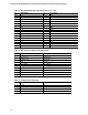


Table Of Contents
- Intel® NUC Board NUC5i5RYB and Intel® NUC Board NUC5i3RYB Technical Product Specification
- Revision History
- Contents
- 1 Product Description
- 1.1 Overview
- 1.2 Online Support
- 1.3 Processor
- 1.4 System Memory
- 1.5 Processor Graphics Subsystem
- 1.5.1 Integrated Graphics
- 1.5.1.1 Intel® High Definition (Intel® HD) Graphics
- 1.5.1.2 Video Memory Allocation
- 1.5.1.3 Mini High Definition Multimedia Interface* (Mini HDMI*)
- 1.5.1.4 Mini DisplayPort*
- 1.5.1.5 Multiple DisplayPort and HDMI Configurations
- 1.5.1.6 High-bandwidth Digital Content Protection (HDCP)
- 1.5.1.7 Integrated Audio Provided by the Mini HDMI and Mini DisplayPort Interfaces
- 1.5.1 Integrated Graphics
- 1.6 USB
- 1.7 SATA Interface
- 1.8 Real-Time Clock Subsystem
- 1.9 Audio Subsystem
- 1.10 LAN Subsystem
- 1.11 Hardware Management Subsystem
- 1.12 Power Management
- 2 Technical Reference
- 2.1 Memory Resources
- 2.2 Connectors and Headers
- 2.2.1 Front Panel Connectors
- 2.2.2 Back Panel Connectors
- 2.2.3 Connectors and Headers (Bottom)
- 2.3 BIOS Security Jumper
- 2.4 Mechanical Considerations
- 2.5 Electrical Considerations
- 2.6 Thermal Considerations
- 2.7 Reliability
- 2.8 Environmental
- 3 Overview of BIOS Features
- 4 Error Messages and Blink Codes
- 5 Regulatory Compliance and Battery Disposal Information
Technical Reference
45
2.2.3.4.3 Power/Sleep LED Header
Pins 2 and 4 can be connected to a one- or two-color LED. Table 19 shows the possible LED
states.
Table 19. States for a Dual-Color Power LED
LED State
Description
Off Power off
Blinking Standby
Steady Normal operation
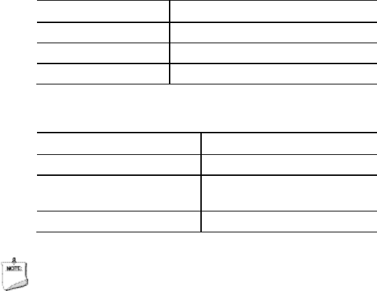
Table 20. States for a Dual-Color Power LED
LED State Description
Off Power off
Secondary color blinking
(amber)
Standby
Primary color steady (white) Normal operation
NOTE
The LED behavior shown in Table 19 is default – other patterns may be set via BIOS setup.
2.2.3.4.4 Power Switch Header
Pins 6 and 8 can be connected to a front panel momentary-contact power switch. The switch
must pull the SW_ON# pin to ground for at least 50 ms to signal the power supply to switch on or
off. (The time requirement is due to internal debounce circuitry on the board.) At least two
seconds must pass before the power supply will recognize another on/off signal.