
Technical product specification


Table Of Contents
- Intel® NUC Board NUC5i5RYB and Intel® NUC Board NUC5i3RYB Technical Product Specification
- Revision History
- Contents
- 1 Product Description
- 1.1 Overview
- 1.2 Online Support
- 1.3 Processor
- 1.4 System Memory
- 1.5 Processor Graphics Subsystem
- 1.5.1 Integrated Graphics
- 1.5.1.1 Intel® High Definition (Intel® HD) Graphics
- 1.5.1.2 Video Memory Allocation
- 1.5.1.3 Mini High Definition Multimedia Interface* (Mini HDMI*)
- 1.5.1.4 Mini DisplayPort*
- 1.5.1.5 Multiple DisplayPort and HDMI Configurations
- 1.5.1.6 High-bandwidth Digital Content Protection (HDCP)
- 1.5.1.7 Integrated Audio Provided by the Mini HDMI and Mini DisplayPort Interfaces
- 1.5.1 Integrated Graphics
- 1.6 USB
- 1.7 SATA Interface
- 1.8 Real-Time Clock Subsystem
- 1.9 Audio Subsystem
- 1.10 LAN Subsystem
- 1.11 Hardware Management Subsystem
- 1.12 Power Management
- 2 Technical Reference
- 2.1 Memory Resources
- 2.2 Connectors and Headers
- 2.2.1 Front Panel Connectors
- 2.2.2 Back Panel Connectors
- 2.2.3 Connectors and Headers (Bottom)
- 2.3 BIOS Security Jumper
- 2.4 Mechanical Considerations
- 2.5 Electrical Considerations
- 2.6 Thermal Considerations
- 2.7 Reliability
- 2.8 Environmental
- 3 Overview of BIOS Features
- 4 Error Messages and Blink Codes
- 5 Regulatory Compliance and Battery Disposal Information
Product Description
19
1.4 System Memory
The board has two 204-pin SO-DIMM sockets and supports the following memory features:
• 1.35 V DDR3L SDRAM SO-DIMMs with gold plated contacts
• Two independent memory channels with interleaved mode support
• Unbuffered, single-sided or double-sided SO-DIMMs
• 16 GB maximum total system memory (with 4 Gb memory technology). Refer to Section 2.1.1
on page 37 for information on the total amount of addressable memory.
• Minimum recommended total system memory: 2048 MB
• Non-ECC SO-DIMMs
• Serial Presence Detect
• DDR3L 1600/1333 MHz SDRAM SO-DIMMs
NOTE
To be fully compliant with all applicable DDR SDRAM memory specifications, the board should be
populated with SO-DIMMs that support the Serial Presence Detect (SPD) data structure. This
allows the BIOS to read the SPD data and program the chipset to accurately configure memory
settings for optimum performance. If non-SPD memory is installed, the BIOS will attempt to
correctly configure the memory settings, but performance and reliability may be impacted or the
SO-DIMMs may not function under the determined frequency.
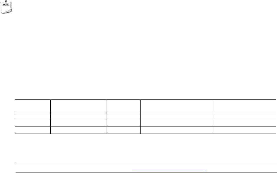
Table 4 lists the supported SO-DIMM configurations.
Table 4. Supported Memory Configurations
DIMM
Capacity
Configuration
(Note)
SDRAM
Density
SDRAM Organization
Front-side/Back-side
Number of SDRAM
Devices
4096 MB
DS
2 Gbit
256 M x8/256 M x8
16
4096 MB
SS
4 Gbit
512 M x8/empty
8
8192 MB
DS
4 Gbit
512 M x8/512 M x8
16
Note: “DS” refers to double-sided memory modules (containing two rows of SDRAM) and “SS” refers to single-sided
memory modules (containing one row of SDRAM).
For information about… Refer to:
Tested Memory http://www.intel.com/NUCSupport