
Intel Xeon Processor Multiprocessor Platform Design Guide

97
Methodology for Determining Topology and Routing Guidelines
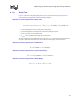
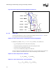
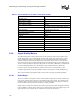
Equation 9-8 can be simplified by defining the clock delay and the clock skew as shown in
Equation 9-9 and Equation 9-10. After simplification, Equation 9-8 is solved for the setup margin
as shown in Equation 9-12.
Equation 9-10. Common Clock Delay
Equation 9-11. Common Clock Skew
Equation 9-12. Common Clock Setup Margin
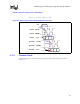
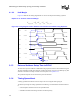
Figure 9-5. Timing Diagram Used to Determine the Common Clock Setup Timing Equations
CLK Out A
CLK Out B
CLK In
A
B
A
B
CLK
CLK
CLK
CLK
CLK
DATA
DATA
T
drv
T
prop
T
setup
T
prop_clk
(A)
T
prop_clk
(B)
T
drv_clk
(B)
T
drv_clk
(A)
T
jitter
T
cycle
T
setup_margin
clkpropclkdrvclk
TTT
__
+=
)()(
_
BTATT
clkclksetupskew
−=
jittersetupskewpropsetupdrvcyclesetupinm
TTTTTTT −−−−−=
__arg