
Intel Xeon Processor Multiprocessor Platform Design Guide

59
Mechanical and EMI Design Considerations
A true Faraday cage would completely surround the source of radiation and contain all radiated
energy. Within the limitations of processor packaging and motherboard assembly it is not possible
to create a true Faraday cage around the processor. By using the heatsink and motherboard ground
plane as two sides of the cage and a metal frame to enclose the remaining four sides, a reasonable
approximation of a Faraday cage can be achieved.
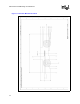
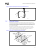
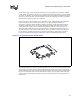
Intel has designed a “picture frame” type of grounding device, called an EMI ground frame, that
fits between the processor and heatsink (see Figure 7-7). With this implementation, it is
unnecessary to design a separate heatsink grounding mechanism, as the frame will provide this
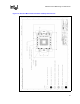
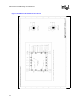
capability. OEMs who choose to use the Intel designed grounding frame will need to provide
ground pads on the top layer of the motherboard around the processor socket (see Figure 7-8).
These pads will provide the necessary ground continuity to complete the Faraday cage. Exact
physical dimensions of the frame and the material used are provided in the processor IGES and
Pro-E models for enabled components. The required motherboard ground pad descriptions are
provided in the Mechanical Design Considerations chapter of this Platform Design Guide.
The EMI ground frame is meant to provide grounding of AC currents seen on the heatsink and has
been shown to be the most effective design in EMI reduction for the processor. The metal frame
will be installed after the processor and retention mechanisms have been inserted. It will fit around
the processor and inside of the retention mechanisms. Fingers on the top of the metal frame will
provide contact to the heatsink, and fingers along the bottom will contact the ground pads on the
motherboard.
Figure 7-7. Conceptual Processor Ground Frame