
Intel Xeon Processor Multiprocessor Platform Design Guide


110
System Theory
Backward crosstalk is present in both stripline and microstrip geometry. The backward-coupled
amplitude is proportional to the backward crosstalk coefficient, the aggressor's signal amplitude,
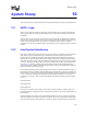
and the coupled length of the network. Backward crosstalk reaches a maximum (and remains
constant) when the propagation time on the coupled network length exceeds one half of the rise
time of the aggressor's signal. Assuming the ideal ramp on the aggressor from 0% to 100% voltage
swing and the rise time on an unloaded coupled network, then the following equation applies.
Equation 10-1. Length for Maximum Backward Crosstalk
An example calculation if fast corner fall time is 1.5 V/ns and board delay is 175 ps/inch (2.1 ns/
foot) follows:
Fall time = 1.5 V/1.5 V/ns = 1 ns
Length of maximum backward crosstalk = ½ * 1 ns * 1000 ps/ns /175 ps/in = 2.86 inches
Agents on the AGTL+ bus drive signals in each direction on the network. This will cause backward
crosstalk from segments on two sides of a driver. The pulses from the backward crosstalk travel
toward each other and will meet and add at certain moments and positions on the bus. This can
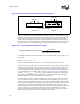
cause the voltage (noise) from crosstalk to double. Table 10-1 provides example coupling factors
for various stripline space to width to dielectric thickness ratios (see Figure 10-4) with dielectric
constant
ε
r
= 4.5, V
OH_MAX
= 1.5 V, and Z
0
= 65 Ω. Note that the fast edge rates of falling edges
place limits on the maximum-coupled length allowable. Also, it should be noted that multiple
parallel-coupled lines will increase the impact on the noise budget.
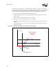
Forward crosstalk is absent in stripline topologies, but present in microstrip. This is for the ideal
case with a uniform dielectric constant. In actual boards, forward crosstalk is nearly absent in
stripline topologies, but abundant in microstrip. The forward coupled amplitude is proportional to
the forward crosstalk coefficient, the aggressor's signal edge rate (dv/dt), and the coupled network's
electrical length. The forward crosstalk coefficient is also a function of the geometry. Unlike
backward crosstalk, forward crosstalk can grow with coupled section length, and may transition in
a direction similar to or opposite to that of the aggressor's edge. Unlike backward crosstalk,
forward crosstalk on the victim signal will continue to grow as it passes through more coupled
length before the aggressor's wave front is absorbed by the termination.
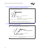
Figure 10-4. Transmission Line Geometry of Microstrip and Stripline
AC GROUND PLANE
A. MICROSTRIP
B. STRIPLINE
DIELECTRIC,
ε
ε
ε
ε
r
DIELECTRIC,
ε
ε
ε
ε
r
SIGNAL LINES
SIGNAL LINES
t
Sp
w
LengthUnitPerDelayBoard
TimeRise
CrosstalkBackwardMaxforLength
×
=
2
1