
Intel Xeon Processor and Intel E7500/E7501Chipset Compatible Platform Design Guide

High-Speed Design Concerns
222 Intel
®
Xeon™ Processor and Intel
®
E7500/E7501 Chipset Compatible Platform Design Guide
SignalX
Processor 0 to Processor 1 PCB Length
and SignalX
Processor 1 to MCH PCB Length
should be chosen
to allow all signals in the same signal group to meet the specific system bus routing guidelines
documented in Chapter 5 of this document. The PLC and SI Adjustment Length motherboard
segments adjust the motherboard trace lengths to account for the processor and MCH package
effects.
Using this relationship, if
SignalX
Processor 0 to Processor 1 PCB Length
and
SignalX
Processor 1 to MCH PCB Length
are known, then SignalY
Processor 0 to Processor 1 PCB Length
and
SignalY
Processor 1 to MCH PCB Length
can be determined using Equation 12-10 and Equation 12-11
respectively.
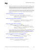
Equation 12-10. SignalY Processor 0/Processor 1 Motherboard Lengths
SignalY
Processor 0 to Processor 1 PCB Length
= SignalX
Processor 0 to Processor 1 PCB Length
– SignalX
Processor PLC
– SignalX
SI Adj
+ SignalY
Processor PLC
+ SignalY
SI Adj
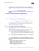
Equation 12-11. SignalY Processor 1/MCH Motherboard Lengths
SignalY
Processor 1 to MCH PCB Length
= SignalX
Processor 1 to MCH PCB Length
– SignalX
Processor PLC
– SignalX
SI Adj
+ SignalY
MCH PLC
+ SignalY
SI Adj
These equations operate by first starting with the known total motherboard length for Signal X and
then subtracting Signal X’s PLC and SI Adjustment Length compensations. The PLC and SI
Adjustment compensations for Signal Y are then added.
12.6.4 System Bus Length Matching Example
Note: Example component values are used in this example and should not be relied upon for actual
design of the system bus.
The system bus 4X data source synchronous signal group requires groups of 17 signals and 2
associated strobes to be length matched within ± 25 mils between components.
Part 1. Given that routing has started with DSTBN0# routed between Processor 0 and Processor 1
with a pin-to-pin route of exactly 5.0 inches, what is the DSTBP0# Processor 0/Processor
1 motherboard length?
Part 2. Given that routing has started with DSTBN0# routed between Processor 1 and MCH with
a pin-to-pin route of exactly 4.0 inches, what is the DSTBP0# Processor 1/MCH
motherboard length?
The processor and MCH package trace lengths can be obtained from the Intel
®
E7501 chipset
System Bus Length Matching Spreadsheet. Contact your Intel representative for information about
the Length Matching Spreadsheet tool. For this example, we will use the following processor and
MCH values:
• Maximum processor package length is this group is 0.578 inch
• DSTBN0# processor package length is 0.208 inch
• DSTBP0# processor package length is 0.134 inch
• Maximum MCH package length is this group is 1.060 inches
• DSTBN0# MCH package length is 0.842 inch
• DSTBP0# MCH package length is 0.738 inch