
Intel Xeon Processor and Intel E7500/E7501Chipset Compatible Platform Design Guide

Platform Power Delivery Guidelines
202 Intel
®
Xeon™ Processor and Intel
®
E7500/E7501 Chipset Compatible Platform Design Guide
11.4.4 Intel
®
ICH3-S Decoupling Recommendations
The ICH3-S is capable of generating large current swings when switching between logic high and
logic low. This condition could cause the component voltage rails to drop below specified limits.
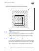
To avoid this, ensure that the appropriate amount of bulk capacitance is added in parallel to the
voltage input pins. It is recommended that the developer use the decoupling capacitors specified in
Table 11-8 to ensure that the component maintains stable supply voltages. The capacitors should be
placed as close to the package as possible (200 mils nominal). It is recommended that for prototype
board designs, the designer include pads for extra power plane decoupling capacitors.
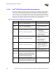
Table 11-8. Intel
®
ICH3-S Decoupling Recommendations
Power Decoupling Requirements Decoupling Placement
V_CPU_IO Use one 0.1 µF decoupling capacitor.
• Locate within 100 mils of the
Intel
®
ICH3-S processor interface
balls.
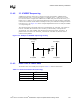
VCCRTC
Use one 1.0 µF decoupling capacitor.
See Figure 9-11 for the External Circuitry.
• Locate within 100 mils of the
VCCRTC interface ball (ball
AB6).
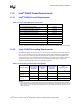
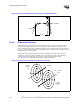
VCC3_3 Requires six 0.1 µF decoupling capacitors.
• Distribute around the ICH3-S
package sides within 100 mils of
the package balls:
– Top near AUX/PCI
– Left across the PCI and LPC
– Bottom near IDE
– Right near GPIO[43]
VCCSus3_3 Requires two 0.1 µF decoupling capacitors.
• Place one capacitor on the top
side within 200 mils of the USB
center.
• Place one capacitor on the
bottom side near the
VCCSus3_3 supply.
VCC1_8 Requires four 0.1 µF decoupling capacitors.
• Locate 2 capacitors distributed
local to the hub interface, within
50 mils of the package HI balls.
• Distribute the remaining
capacitors on the left and bottom
sides of the package for core
delivery.
VCCSus1_8 Requires one 0.1 µF decoupling capacitor.
• Locate within 200 mils of the
ICH3-S, Balls B23 and C23.
5VREF_SUS
Requires one 0.1 µF decoupling capacitor.
V5REF_SUS is the reference voltage for some 5 V
tolerant inputs in the ICH3-S (USB data and over
current signals). VCCSus3_3 must never exceed
0.7 V higher than V5REF_SUS. For most platforms,
this power sequencing is not an issue as
VCCSus3_3 is derived from 5VREF_SUS.
V5REF
Requires one 0.1 µF decoupling capacitor.
V5REF is the reference voltage for most 5 V tolerant
inputs in the ICH3-S. Tie to pins V5REF[2:1]. V5REF
must power up before or simultaneous to VCC3_3. It
must power down after or simultaneous to VCC3_3.