
Intel Xeon Processor and Intel E7500/E7501Chipset Compatible Platform Design Guide

Platform Power Delivery Guidelines
182 Intel
®
Xeon™ Processor and Intel
®
E7500/E7501 Chipset Compatible Platform Design Guide
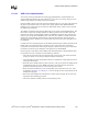
11.2.5 VR Down Recommendations
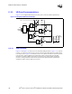
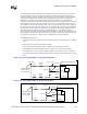
Figure 11-6 is a simplified block diagram of a four-phase, interleaved VRD implementation.
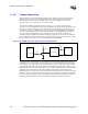
11.2.5.1 VRD Placement
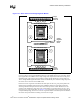
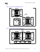
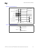
Figure 11-7 and Figure 11-8 show the two recommended VRD placements. Figure 11-7 is referred
to as the “L” pattern since it has the two processor sockets and the VRD placed in an offset manner
in the shape of an L. Figure 11-8 is referred to as the “row” pattern since the two sockets are placed
in the same line, with the VRD directly beneath both sockets. The advantage of both VRD
placements are that the VRD current can flow to both processor sockets without overlapping
currents or causing interference between both sockets. These placements also minimize and
equalize the distance from the VRD to each socket.
Figure 11-6. Simplified VRD Circuit Example
Driver
A
Driver
B
Driver
C
Driver
D
Controller
VID
PWRGD
OUTEN
clks
12 V
VCC_CPU