
Intel Xeon Processor and Intel E7500/E7501Chipset Compatible Platform Design Guide

Intel
®
Xeon™ Processor and Intel
®
E7500/E7501 Chipset Compatible Platform Design Guide 133
Intel
®
82870P2 (P64H2)
8.2.7.7 Hot-Plug Multiplexed Signals in Dual-Slot Parallel Mode
The Hot-Plug signals that connect to the controller are listed in Table 8-19. In Table 8-19 the
“Signal” column refers to the name of the slot pin when in dual-slot mode. The “Bus A” and
“Bus B” columns represent the corresponding P64H2 pins.
NOTES:
1. HPx_SLOT[N] are pull-ups/pull-downs. When in dual-slot parallel mode, the external logic that decodes the
three-state value of PCIXCAP from the card must actively drive these signals to either logic 1 or logic 0 to
overcome the value of the pull-up/pull-down, and must be tri-stated during reset and while the card is not
connected to avoid damaging the slot count value.
2. HPx_SID must be pulled down on the system board when configuring the P64H2 for dual-slot parallel mode
so that the LED for slot B on busses A and B remain off during reset.
3. The P64H2 must drive this signal to the corresponding state shown in Table 8-18 in case the system is set up
for dual-slot parallel mode so that LEDs are in the appropriate state (off), and the Q-switches remain
disconnected. Note that the placement of the signals should be such that the value driven by the P64H2 in
dual-slot parallel mode is the same value it would have driven if in serial mode.
4. In both parallel modes, the BUSEN# and CLKEN# signals become active low instead of active high, as they
are during serial mode.
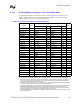
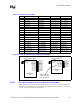
Table 8-19. Dual-Slot Parallel Mode Hot-Plug Signals Table
Signal Type
Multiplexed Intel
®
P64H2 Pin
Note
Bus A Ball # Bus B Ball #
HxSWITCHA I PAIRQ15 F4 PBIRQ15 F1
HxFAULTA# I PAIRQ14 E4 PBIRQ14 E1
HxPRSNT2A# I PAIRQ13 F5 PBIRQ13 D1
HxPRSNT1A# I PAIRQ12 E5 PBIRQ12 C1
HxM66ENA I/O PAIRQ11 D5 PBIRQ11 B1
HxPCIXCAP1A I HPA_SLOT2 D20 HPB_SLOT2 D22 1
HxPCIXCAP2A I HPA_SLOT1 C20 HPB_SLOT1 C23 1
HxRESETA# O PAGNT5 E22 PBGNT5 G4 3
HxGNLEDA O HPA_SOC A19 HPB_SOC A24 3
HxAMLEDA O HPA_SOL D19 HPB_SOL C22 3
HxBUSENA# O HPA_SORR# A18 HPB_SORR# A22 3, 4
HxCLKENA# O HPA_SIL# C21 HPB_SIL# D24 3, 4
HxPWRENA O HPA_SOD B19 HPB_SOD C24 3
HxSWITCHB I PAIRQ10 C5 PBIRQ10 F2
HxFAULTB# I PAIRQ9 B5 PBIRQ9 E2
HxPRSNT2B# I PAIRQ8 A5 PBIRQ8 D2
HxPRSNT1B# I PAREQ5 F24 PBREQ5 G3
HxM66ENB I/O PAREQ4 F21 PBREQ4 H4
HxPCIXCAP1B I PAREQ3 F19 PBREQ3 H2
HxPCIXCAP2B I HPA_SLOT0 A20 HPB_SLOT0 B2 1
HxRESETB# O HPA_SOR# B18 HPB_SOR# A21 3
HxGNLEDB O HPA_SIC A23 HPB_SIC A23 3
HxAMLEDB O HPA_SID B24 HPB_SID B24 2
HxBUSENB# O PAGNT4 F23 PBGNT4 H5 3, 4
HxCLKENB# O PAGNT3 F20 PBGNT3 H3 3, 4
HxPWRENB O HPA_SOLR C19 HPB_SOLR B22 3