
Intel Xeon Processor and Intel E7500/E7501Chipset Compatible Platform Design Guide

Intel
®
82870P2 (P64H2)
122 Intel
®
Xeon™ Processor and Intel
®
E7500/E7501 Chipset Compatible Platform Design Guide
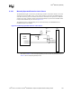
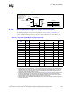
8.1.8 IDSEL Implementation
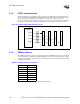
Designers should use a 100 Ω series coupling resistor on the IDSEL signal when implementing
PCI-X. Though the PCI-X Addendum PCI Local Bus Specification, Revision 1.0 calls for a 2 k
Ω
resistor, the current specification, PCI-X Addendum to the PCI Local Bus Specification,
Revision 1.0a allows for other resistor values. See Figure 8-11 for an example of how to implement
the coupling resistor. IDSEL mapping per P64H2 pin is arbitrary. However, AD16 is reserved.
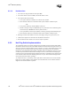
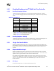
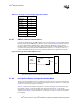
8.1.9 SMBus Address
The SMBus interface does not have configuration registers. The SMBus address is set by the states
of pins PAGNT[5:4] and PBGNT[5:4] when PWROK is asserted as described in Table 8-14. Refer
to the Intel
®
82870P2 PCI/PCI-X 64-bit Hub 2 (P64H2) Datasheet for a more detailed description
of P64H2 strap latching.
NOTE: There is no bit 0 because it is the read/write direction indicator.
Figure 8-11. IDSEL Sample Implementation Circuit
Intel
®
P64H2
IDSEL0
IDSEL1
IDSEL2
IDSEL3
100 Ω
PCI SLOT 1
PCI SLOT 3
PCI SLOT 4
PCI SLOT 2
100 Ω
100 Ω
100 Ω
Table 8-14. SMBus Address Configuration
Bit Value
71
61
5PAGNT5
40
3PAGNT4
2PBGNT5
1PBGNT4