
Embedded Voltage Regulator-Down (EmVRD) 11.0 Design Guidelines for Embedded Implementations Supporting PGA478

EmVRD 11.0—9.0
Embedded Voltage Regulator-Down (EmVRD) 11.0
Design Guidelines for Embedded Implementations January 2007
42
To avoid performance degradation resulting from EmVRD over-temperature conditions,
VR11 PWM controllers include a signal called VR_FAN. This signal is activated at 90%
of the max VR_HOT trip point. It provides the system designer with options to perform
thermal management activities, such as fan speed control, in order to avoid initiating
performance degradation.
The controller is located away from the EmVRD ‘hot spot’; therefore, external
thermistors are needed to sense temperature. Thermistors are placed in the
temperature sensitive region of the voltage regulator. The location must be chosen
carefully and is to represent the position where initial thermal violations are expected
to occur. When exceeded, the thermal monitor circuit is to initiate FORCEPR# to
protect the voltage regulator from heat damage.
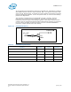
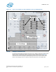
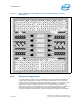
Figure 14. FORCEPR# Buffering
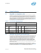
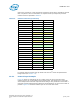
Table 19. FORCEPR# Specifications
Parameter Minimum Typical Maximum
V
CCP
- Vccp
1
-
V
CCP
termination resistance 25 Ω -70 Ω
FORCEPR# leakage current - - 200 mA
FORCEPR# Transition time 1.10 ns 100 ns -
Minimum time to toggle in and out of D-VID 0.5 ms - -
1. Consult Table 12 for V
CCP
specifications.
Q1
3904
130
Ω
FORCEPR##
VR_HOT