
Embedded Voltage Regulator-Down (EmVRD) 11.0 Design Guidelines for Embedded Implementations Supporting PGA478

EmVRD 11.0—6.0
Embedded Voltage Regulator-Down (EmVRD) 11.0
Design Guidelines for Embedded Implementations January 2007
36
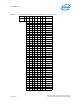
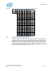
6.1.1 Voltage Identification Table
The VID table in Table 17 has the mapping of the VID pins between the CPU and the VR
controller and the codes that the processors use. The table also has codes from 1.6 V to
1.5125 V that processors will not use.
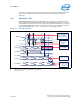
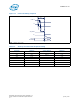
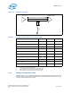
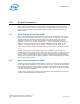
Figure 13. D-VID Bus Topology
Table 16. VID Buffer And VID Bus Electrical Parameters
Design Parameter Minimum Typical Maximum
VID Bus Voltage - Vccp
1
-
Voltage Limits At Processor VID Pins - 0.100 - Vccp
2
VIH 0.8 V - -
VIL - - 0.3 V
L1, VID trace length 0.5 inch - 15 inches
L2, Vccp Stub Length 0 inch - 1 inch
VID trace length skew - 1.0 inch -
VID trace width 5 mil - -
VID trace separation 5 mil - -
RTT, Pull-Down Resistor 1900 Ω
3
2000 Ω 2100 Ω
4
Notes:
1. Consult Table 9 for Vccp specifications.
2. Consult the processor datasheet for signal overshoot limits.
3. Value represents minimum resistance at tolerance limits.
4. Value represents maximum resistance at tolerance limits.
R
TT
Processor PWM Controller
L
1
L
2