
Embedded Voltage Regulator-Down (EmVRD) 11.0 Design Guidelines for Embedded Implementations Supporting PGA478

Embedded Voltage Regulator-Down (EmVRD) 11.0
January 2007 Design Guidelines for Embedded Implementations
29
3.0—EmVRD 11.0
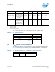
Table 13 lists test pins for V
CCP
at the processor and Intel
®
E7520 Chipset.
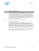
3.2 V
CCP
Bypass Recommendations
The values and placement recommendations for the V
CCP
decoupling capacitors are in
Table 14. These values and quantities are for a switching regulator. In all cases the
capacitors should be placed as close as possible to the device.
Table 12. V
CCP
Specifications
Number of CPU
Sockets
Processor
V
CCP
Min
V
CCP
Typ
V
CCP
Max
Itt
Min
1
Itt
Max
2
Itt
Max
3
One Socket Design
2
Dual-Core Intel
®
Xeon
®
Processor LV,
and Dual-Core Intel
®
Xeon
®
Processor ULV
and Intel
®
Celeron
®
Processor 1.66 GHz /
1.83 GHz
0.9975 V 1.05 V 1.1025 V 0.15 A 6 A 2.5 A
Two Socket Design
2
Dual-Core Intel
®
Xeon
®
Processor LV
and Dual-Core Intel
®
Xeon
®
Processor ULV
and Intel
®
Celeron
®
Processor 1.66 GHz /
1.83 GHz
0.9975 V 1.05 V 1.1025 V 0.3 A 12 A 5 A
Notes:
1. These values are pre-silicon estimates and are subject to change.
2. Before V
CC
is stable.
3. After V
CC
is stable.
4. Includes the MCH and other circuitry.
5. Itt and I
CCP
are synonymous.
Table 13. V
CCP
Measurement Pins
Device Supply Pins
Processor V
CCP
AF26
Processor Vss AE26
Intel
®
E7520 Chipset V
CCP
(V
TT
)A31
Intel
®
E7520 Chipset V
SS
B32
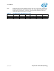
Table 14. V
CCP
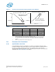
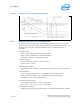
Bypass Capacitors TD7: Regulation to Power Down Delay
Cap Location CPU Socket MCH Regulator
0.1 uF 8 4 2
330 uF 1 1 1