
Embedded Voltage Regulator-Down (EmVRD) 11.0 Design Guidelines for Embedded Implementations Supporting PGA478

EmVRD 11.0—3.0
Embedded Voltage Regulator-Down (EmVRD) 11.0
Design Guidelines for Embedded Implementations January 2007
28
3.0 V
CCP
Requirements
The V
CCP
regulator provides power to the processor VID pull-up resistors, the chipset -
processor front side bus, and miscellaneous buffer signals. This rail voltage must
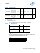
converge to the amplitude defined in Table 9 to begin power sequencing. The EmVRD
controller will sense the amplitude of the V
CCP
rail and initiate power sequencing upon
crossing a defined threshold voltage. The V
CCP
regulator controller start up can be
inhibited until various system checks can be verified, usually by way of discrete logic.
In a dual-processor design this could include ensuring a boot processor is installed.
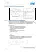
Once the V
CCP
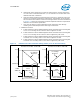
regulator is allowed to start, valid output voltage of Table 9 must be
guaranteed by the timing protocol defined in Figure 10.
Note: Note: V
CCP
is often referred to as V
TT
on other Intel Processors.
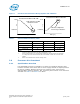
3.1 Electrical Specifications
If a system design will use only one embedded processor a linear regulator is
recommended for the V
CCP
supply. If the system design will use two embedded
processors, a switching regulator is recommended. With either supply method, the
design must have adequate decoupling capacitors to ensure the sum of AC bus noise
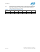
and DC tolerance satisfies limits identified in Table 9. The processor and chipset V
CCP
supply must be maintained within these tolerance limits across full operational thermal
limits, part-to-part component variation, age degradation, and regulator accuracy. Full
bandwidth bus noise amplitude must be guaranteed across all V
CC
/V
SS
pin pairs defined
in Table 10.
The V
CCP
supply must be unconditionally stable under all DC and transient conditions
across the voltage and current ranges defined in Table 9. The V
CCP
supply must also
operate in a no-load condition: i.e., with no processor installed.