
Embedded Voltage Regulator-Down (EmVRD) 11.0 Design Guidelines for Embedded Implementations Supporting PGA478

Embedded Voltage Regulator-Down (EmVRD) 11.0
January 2007 Design Guidelines for Embedded Implementations
21
2.0—EmVRD 11.0
d. Undershoot during maximum to minimum VID transition must be limited to 5
mV. This 5 mV is included within the +/-5 mV tolerance on the final VID value
defined under test condition A.
e. Overshoot observed when transitioning from minimum to maximum VID must
conform to overshoot specifications. Specifically, superposition of the dynamic
VID overshoot event and the overshoot resulting from the transient test defined
in Section 2.6 must not exceed the overshoot amplitude and time requirements
defined in the overshoot specification.
f. Care must be taken to avoid motherboard and component heat damage
resulting from extended operations with high current draw.
2. Validation exercises:
a. D-VID transition must be validated against above constraints from a starting VID
of 1.5 V to an ending VID of 0.8375 V with an applied 5 A Load.
b. D-VID transition must be validated against above constraints from a starting VID
of 1.5 V to an ending VID of 0.8375 V with an applied VR_TDC Load.
c. D-VID transition must be validated against above constraints from a starting VID
of 0.8375 V to an ending VID of 1.5 V with an applied 5 A Load.
d. D-VID transition must be validated against above constraints from a starting VID
of 0.8375 V to an ending VID of 1.5 V with an applied VR_TDC Load.
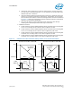
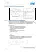
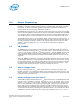
Figure 6. EmVRD 11.0 D-VID Transition Timing States (12.5 mV VID Resolution)
Vcc
Time (μs)
1.5 V1.5 V
0.8375 V
Initial
VID Code
Final
VID Code
Initial
VID Code
Final
VID Code
315
μs Maximum
315μ s Maximum
50μs
662.5 mV
Vcc
Time (μs)
Transition From Max To Min VID
Transition From Min To Max VID
50μs
Vcc Voltage
Response
Vcc Voltage
Response
662.5 mV
0.8375 V
265μs
265
μs