
Embedded Voltage Regulator-Down (EmVRD) 11.0 Design Guidelines for Embedded Implementations Supporting PGA478


Embedded Voltage Regulator-Down (EmVRD) 11.0
January 2007 Design Guidelines for Embedded Implementations
17
2.0—EmVRD 11.0
• The controller should support voltage amplitudes read across sense elements with
a DCR of 0.1 – 2.0 m
Ω. Controller vendors should define the minimum sense signal
voltage necessary to satisfy their controller signal to noise ratio requirements.
These requirements are to be published by the vendor in their controller datasheet.
• Vendors should establish an inductor DCR sense topology that supports a ±19 mV
TOB @ 1.25 VID, 36 A I
CCMAX
, 2.1 mΩ processor load line slope including voltage
ripple. The topology and component values are to be published in the controller
datasheet.
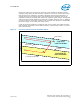
2.3.2 Dynamic Voltage Identification (D-VID) TOB
During the D-VID mode of operation (see Section 2.5), EmVRD minimum voltage
tolerance band requirements must be satisfied. The minimum voltage cannot fall below
the values predicted by Equation 3 assuming any possible VID setting along with the
RLL at TOB values defined in Table 3. Dynamic VID max/min limits are expanded during
VID transition and are a function of the starting VID and the final VID.
For low to higher VID transitions, the max/min limits can be calculated by:
•Vcc
START_LOWER_TOB =VIDSTARTING - RLL*Icc - TOB
•Vcc
FINAL_UPPER_TOB =VIDFINAL - RLL*Icc
For high to low VID transitions, the max/min limits are calculated by:
•Vcc
START_UPPER_TOB =VIDSTARTING - RLL*Icc
•Vcc
FINAL_LOWER_TOB =VIDFINAL - RLL*Icc - TOB
V
CCMAX
EmVRD TOB can be relaxed during dynamic VID. Positive tolerance variation is
permitted and is to be bounded by the voltages predicted by Equation 1 in Table 3,
where VID is the standard VID value in regulation when not in the D-VID mode.
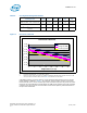
2.3.3 Ripple Voltage
To meet tolerance band specifications, high and low frequency ripple is to be limited to
10 mV peak-to-peak. Measurements must be taken carefully to ensure that
superposition of high frequency with low frequency oscillations do not sum to a value
greater than 10 mV peak-to-peak. Measurements are to be taken with a 20 MHz band
limited oscilloscope. Ripple is to be measured under both VTT and processor loading
conditions. VTT testing is to be performed at 5 A minimum loading and at VR_TDC.
Processor testing is to be evaluated while running the MaxPower application and with
the operating system in an idle state with no other applications running.
Contact your Intel field sales representative for the version of MaxPower that applies to
this processor family.
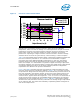
2.3.4 Sense Topology Requirements
EmVRD designers must construct a sense topology that guarantees compliance to
tolerance band specifications under standard operation and under the D-VID mode of
operation. This includes selection of sense elements and supporting components that
satisfy tolerance requirements with the chosen EmVRD controller and ripple amplitude.
Inductor DCR or resistor current sensing topologies are required to satisfy tolerance
band requirements. Current sensing across MOSFET RDSon is not recommended for
load line AVP functions due to the large variation in this parameter. Evaluation of this
sense method has shown that the TOB requirements cannot be satisfied unless
expensive <10% tolerance MOSFETs are chosen.