
Embedded Voltage Regulator-Down (EmVRD) 11.0 Design Guidelines for Embedded Implementations Supporting PGA478


EmVRD 11.0—2.0
Embedded Voltage Regulator-Down (EmVRD) 11.0
Design Guidelines for Embedded Implementations January 2007
16
2.3 Voltage Tolerance Band (TOB)
Processor load line specifications must be guaranteed across component process
variation, system temperature extremes, and age degradation limits. The EmVRD
topology and component selection must maintain a 3*
σ tolerance of the EmVRD
Tolerance Band around the typical load line. The critical parameters include voltage
ripple, EmVRD controller tolerance, and current sense tolerance under both static and
transient conditions. Individual tolerance components vary among designs; the
processor requires only that the total error stack-up stay within the defined EmVRD
configuration tolerance band under the conditions defined in Table 4.
2.3.1 EmVRD Controller Requirements
The vendor for the chosen EmVRD controller, typically a pulse width modulator
controller (PWM) should publish data and collateral that is critical for satisfying design
requirements. This includes support of the following:
• The controller vendors are to define equations for calculating the EmVRD TOB with
Inductor DCR for current sensing and/or output series resistor sensing. The
equations are to include all parameter dependencies such as adaptive voltage
positioning (AVP) tolerances, age degradations, thermal drifts, sense element’s DC
and AC accuracy, etc. under 3*
σ variation. These equations should be published in
the controller datasheet. The vendor is to distribute and support a tolerance band
calculator that communicates the voltage regulator TOB for each valid VID.
• Total controller DC set point accuracy is to be <0.5% over temperature, component
age, and lot to lot variation over the 1.0 – 1.5 V VID range. DAC accuracy may be
larger for voltages below 1V under the assumption that the required Vmin TOB
requirements are always satisfied. Typical low voltage accuracy is ±5 mV for 0.8 V
– 1.0 V and ±8 mV < 0.8 V. Each vendor is to publish their controller DAC accuracy
by VID value in the component datasheet.
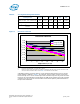
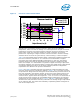
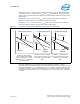
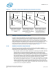
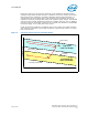
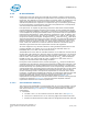
Figure 4. Examples of High Volume Manufacturing Compliant Load Lines
Example A: Measured load line
satisfies slope specification
and is centered in the LL
window
Example B: When component
tolerances shift the load line to
the lower TOB limits, the 3-σ
manufacturing LL is bounded by
the Vccmin LL
Example C: When component
tolerances shift the load line to
the upper TOB limits, the 3-σ
manufacturing load line is
bounded by the Vccmax LL
Vccmax LL Vccmax LL
Vccmax LL
Measured Load Line
3-σ Manufacturing LL 3-σ Manufacturing LL
Vccmin LL Vccmin LL Vccmin LL