
Embedded Voltage Regulator-Down (EmVRD) 11.0 Design Guidelines for Embedded Implementations Supporting PGA478


Embedded Voltage Regulator-Down (EmVRD) 11.0
January 2007 Design Guidelines for Embedded Implementations
15
2.0—EmVRD 11.0
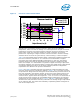
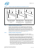
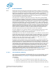
Example A in Figure 3 shows a load line that is contained in the specification window
and in this instance, complies with V
CCMIN
and V
CCMAX
specifications. The positioning of
this processor load line will shift up and down as the tolerance drifts from typical to the
design limits.
Example B in Figure 3 shows that V
CCMAX
limits will be violated as the component
tolerances shift the load line to the upper tolerance band limits.
Example C in Figure 3 shows that the V
CCMIN
limits will be violated as the component
tolerances shift the load line to the lower tolerance band limits.
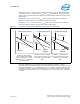
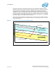
To satisfy specifications across high volume manufacturing variation, a typical
processor load line must be centered in the load line window and have a slope equal to
the value specified in Figure 3. Example A in Figure 4 shows a processor load line that
meets this condition. Under full 3*
σ tolerance band variation, the load line slope will
intercept the V
CCMIN
load line (Figure 4 Example B) or V
CCMAX
load line (Figure 4 Example
C) limits.
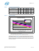
Figure 3. Examples of High Volume Manufacturing Load Line Violations
Example A: This load line
satisfies voltage limits, but will
violate specifications as the VR
TOB varies across the minimum
to maximum range
Example B: Vccmax violation
when component tolerance shift
Load Line to the upper TOB
limits
Example C: Vccmin violation
when component tolerance shift
Load Line to the lower TOB
limits
Vccmin LL
Vccmax LL Vccmax LL Vccmax LL
Vccmin LL Vccmin LL
Measured Load Line 3-σ Manufacturing LL 3-σ Manufacturing LL
Vccmax
Violation
Vccmin
Violation