
Embedded Voltage Regulator-Down (EmVRD) 11.0 Design Guidelines for Embedded Implementations Supporting PGA478


EmVRD 11.0—2.0
Embedded Voltage Regulator-Down (EmVRD) 11.0
Design Guidelines for Embedded Implementations January 2007
14
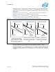
Since each processor uses a processor load line, the voltage measurement points for
accurate load line determination is at the processor V
CCSENSE
and V
SSSENSE
pins. The
use of a BGA type socket for the processor would dictate that the load line
measurements be taken on the back side of the circuit board on the vias connected to
the sense signals.
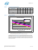
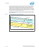
To properly calibrate the processor load line parameter, the EmVRD designer must
excite the processor socket with a current step that generates a voltage response which
must be checked against the load line window requirements as shown in Figure 2.
Table 6 identifies the steady state and transient current values to use for this
calibration. For additional information, consult the processor load line calculator for the
appropriate Intel processor.
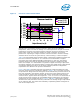
EmVRD designs must be processor load-line compliant across the full tolerance band
window to avoid data corruption, system lock-up, and reduced performance. When
validating a system’s processor load line, a single measurement is statistically
insignificant and cannot represent the response variation seen across the entire high
volume manufacturing population of EmVRD designs. A typical processor load line may
fit in the specification window; although designs residing elsewhere in the tolerance
band distribution may violate the specifications.
Table 5. Processor Load-Line Window
I
CC
(A) V
CCMAX
(V) V
CCTYP
(V) V
CCMIN
(V)
0 0.019 0.000 -0.019
5 0.009 -0.011 -0.030
10 -0.002 -0.021 -0.040
15 -0.013 -0.032 -0.051
20 -0.023 -0.042 -0.061
25 -0.034 -0.053 -0.072
30 -0.044 -0.063 -0.082
35 -0.055 -0.074 -0.093
40 -0.065 -0.084 -0.103
45 -0.076 -0.095 -0.114
Notes:
1. Presented as a deviation from VID
2. Processor load line slope = 2.1 m
Ω, TOB = 19 mV
3. Consult Table 4 for maximum current values
4. Consult Table 3 for linear equations for Vcc
MAX, VccTYP, and
Vcc
MIN
Table 6. Current Step Values for Transient Processor Load Line Testing
VR Configuration Starting Current Ending Current
Dynamic
Current Step
Dual-Core Intel
®
Xeon
®
Processor LV 23.6 A 36 A 12.4 A
Dual-Core Intel
®
Xeon
®
Processor ULV 13.3A 19A 5.7 A
Intel
®
Celeron
®
Processor 1.66 GHz / 1.83
GHz
23.6 A 36A 12.4 A