
Embedded Voltage Regulator-Down (EmVRD) 11.0 Design Guidelines for Embedded Implementations Supporting PGA478


EmVRD 11.0—2.0
Embedded Voltage Regulator-Down (EmVRD) 11.0
Design Guidelines for Embedded Implementations January 2007
12
Notes:
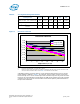
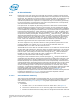
1. Presented as a deviation from VID
2. Processor load line Slope = 2.1 mΩ, TOB = 19 mV
3. Dual-Core Intel
®
Xeon
®
Processor ULV IccMAX is limited to 19A and Intel
®
Celeron
®
Processor 1.66
GHz / 1.83 GHz is limited to 36A, consult Table 4 for maximum current values
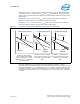
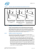
A EmVRD transient processor load line circuit should be designed to meet or exceed
rated conditions defined in Table 4. For example, the processor requires a processor
load-line slope of 2.1 mΩ. A transient processor load line slope can vary from the static
load-line, but it should always reside within the TOB range. However, the static load line
condition must be set to the recommended value unless explicitly stated otherwise in
the processor datasheet.
Table 4.
V
CC
Regulator Design Parameters
VR Configuration I
CCMAX
Dynamic
I
CC
RLL TOB
Maximum
VID
Minimum
VID
Dual-Core Intel
®
Xeon
®
Processor LV 36 A 12.4 A 2.1 mΩ 19 mV 1.25 1.1125
Dual-Core Intel
®
Xeon
®
Processor ULV 19 A 5.7A 2.1 mΩ 19 mV 1.2125 1.0
Intel
®
Celeron
®
Processor 1.66 GHz /
1.83 GHz
36 A 12.4 A 2.1 mΩ 19 mV 1.275 1.1125
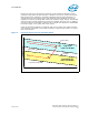
Figure 1. Processor Load Line
Processor Load Line
-0.12
-0.10
-0.08
-0.06
-0.04
-0.02
0.00
0.02
0.04
0 5 10 15 20 25 30 35
Output Current, Icc (A)
Offset from VID (V)
Vccmax (V)-VID
Vcctyp (V)-VID
Vccmin (V)-VID