
Technical Product Specification


Intel Desktop Board DN2800MT Technical Product Specification
40
1.13.2.1 Power Input
When resuming from an AC power failure, the computer returns to the power state it
was in before power was interrupted (on or off). The computer’s response can be set
using the Last Power State feature in the BIOS Setup program’s Boot menu.
For information about Refer to
The location of the internal power connector Figure 13, page 47
The signal names of the internal power connector Table 34, page 58
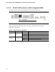
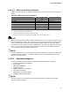
1.13.2.2 Fan Headers
The function/operation of the fan headers are as follows:
• The fan is on when the board is in the S0 state
• The fan is off when the board is off or in the S3, S4, or S5 state.
• The fan header is wired to a fan tachometer input of the hardware monitoring and
fan control ASIC.
• The fan header supports closed-loop fan control that can adjust the fan speed as
needed.
• The fan header has a +12 V DC connection.
• Supports 3-wire (voltage controlled) and 4-wire (Pulse Width Modulation
controlled) fans.
Boards with AA number G23738-600 have a 3-wire system fan header.
Boards with AA number G23738-800 (and later) have 3-wire and 4-wire fan
headers.
For information about Refer to
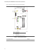
The location of the fan headers Figure 13, page 47
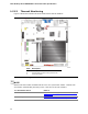
The location of the fan headers and
sensor for thermal monitoring
Figure 9, page 36
3-wire and 4-wire fan headers http://www.intel.com/support/motherboards/desktop/sb
/cs-012074.htm
Product Change Notification http://qdms.intel.com/dm/d.aspx/82B7ABB2-832F-410F-
89D4-9FF096699E18/PCN111258-02.pdf