Intel® Desktop Board DN2800MT Technical Product Specification October 2013 Order Number: G39091-009 The Intel Desktop Board DN2800MT may contain design defects or errors known as errata that may cause the product to deviate from published specifications. Current characterized errata are documented in the Intel Desktop Board DN2800MT Specification Update.
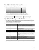
Revision History Revision Revision History Date ® -001 First release of the Intel Specification Desktop Board DN2800MT Technical Product December 2011 -002 Updated the Board Identification Information section and added a spec clarification April 2012 -003 Specification Clarification June 2012 -004 Specification Clarification August 2012 -005 Specification Clarification October 2012 -006 Specification Clarification March 2013 -007 Specification Clarification May 2013 -008 Specificat
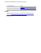
Board Identification Information Basic Desktop Board DN2800MT Identification Information AA Revision BIOS Revision Notes G23738-600 MTCDT10N.86A.0146 1,2 G23738-800 MTCDT10N.86A.0152 1,2 G23738-801 MTCDT10N.86A.0152 1,2 G23738-802 MTCDT10N.86A.0159 1,2 Notes: 1. The AA number is found on a small label on the component side of the board. 2.
Intel Desktop Board DN2800MT Technical Product Specification For information about Refer to 3-wire and 4-wire fan headers http://www.intel.com/support/motherboards/desktop/sb /cs-012074.htm Product Change Notification http://qdms.intel.com/dm/d.aspx/82B7ABB2-832F-410F89D4-9FF096699E18/PCN111258-02.pdf Errata Current characterized errata, if any, are documented in a separate Specification Update. See http://www.intel.com/content/www/us/en/motherboards/desktopmotherboards/motherboards.
Preface This Technical Product Specification (TPS) specifies the board layout, components, connectors, power and environmental requirements, and the BIOS for Intel® Desktop Board DN2800MT. Intended Audience The TPS is intended to provide detailed, technical information about Intel Desktop Board DN2800MT and its components to the vendors, system integrators, and other engineers and technicians who need this level of information. It is specifically not intended for general audiences.
Intel Desktop Board DN2800MT Technical Product Specification Other Common Notation vi # Used after a signal name to identify an active-low signal (such as USBP0#) GB Gigabyte (1,073,741,824 bytes) GB/s Gigabytes per second Gb/s Gigabits per second KB Kilobyte (1024 bytes) Kbit Kilobit (1024 bits) kbits/s 1000 bits per second MB Megabyte (1,048,576 bytes) MB/s Megabytes per second Mbit Megabit (1,048,576 bits) Mbits/s Megabits per second TDP Thermal Design Power xxh An address or
Contents Revision History Board Identification Information .................................................................. iii Specification Changes or Clarifications .......................................................... iii Errata ......................................................................................................iv Preface Intended Audience..................................................................................... v What This Document Contains..........................
Intel Desktop Board DN2800MT Technical Product Specification 1.13 Power Management .......................................................................... 37 1.13.1 ACPI .................................................................................... 37 1.13.2 Hardware Support ................................................................. 39 2 Technical Reference 2.1 Memory Resources ........................................................................... 43 2.1.1 Addressable Memory .........
Contents 4 Error Messages and Beep Codes 4.1 4.2 4.3 4.4 4.5 Speaker .......................................................................................... 87 BIOS Beep Codes ............................................................................. 87 Front-panel Power LED Blink Codes ..................................................... 88 BIOS Error Messages ........................................................................ 88 Port 80h POST Codes ...........................................
Intel Desktop Board DN2800MT Technical Product Specification Tables 1. 2. 3. 4. 5. 6. 7. 8. 9. 10. 11. 12. 13. 14. 15. 16. 17. 18. 19. 20. 21. 22. 23. 24. 25. 26. 27. 28. 29. 30. 31. 32. 33. 34. 35. 36. 37. 38. 39. 40. 41. 42. 43. 44. x Feature Summary ............................................................................. 13 Components Shown in Figure 1 .......................................................... 16 Components Shown in Figure 2 .......................................................
Contents 45. 46. 47. 48. 49. 50. 51. 52. 53. 54. 55. 56. 57. Acceptable Drives/Media Types for BIOS Recovery................................ 81 Boot Device Menu Options ................................................................. 82 Master Key and User Hard Drive Password Functions ............................ 84 Supervisor and User Password Functions ............................................. 85 BIOS Beep Codes .............................................................................
Intel Desktop Board DN2800MT Technical Product Specification xii
1 Product Description 1.1 Overview 1.1.1 Feature Summary Table 1 summarizes the major features of the board. Table 1. Feature Summary Form Factor Mini-ITX (6.7 inches by 6.7 inches [170.18 millimeters by 170.
Intel Desktop Board DN2800MT Technical Product Specification Table 1. Feature Summary (continued) Peripheral Interfaces • Ten USB 2.
Product Description 1.1.2 Board Layout (Top) Figure 1 shows the location of the major components on the top-side of the Intel Desktop Board DN2800MT. Figure 1.
Intel Desktop Board DN2800MT Technical Product Specification Table 2 lists the components identified in Figure 1. Table 2.
Product Description 1.1.3 Board Layout (Bottom) Figure 2 shows the location of the major components on the bottom-side of the Intel Desktop Board DN2800MT. Figure 2. Major Board Components (Bottom) Table 3.
Intel Desktop Board DN2800MT Technical Product Specification 1.1.4 Block Diagram Figure 3 is a block diagram of the major functional areas of the board. Figure 3.
Product Description 1.2 1.3 Online Support To find information about… Visit this World Wide Web site: Intel Desktop Board DN2800MT http://www.intel.com/products/motherboard/index.htm Desktop Board Support http://www.intel.com/p/en_US/support?iid=hdr+support Available configurations for Intel Desktop Board DN2800MT http://ark.intel.com Chipset information http://www.intel.com/products/desktop/chipsets/index.htm BIOS and driver updates http://downloadcenter.intel.com Tested memory http://www.
Intel Desktop Board DN2800MT Technical Product Specification 1.4 System Memory The board has two 204-pin SO-DIMM sockets and supports the following memory features: • • • • • • 1.
Product Description Table 4 lists the supported SO-DIMM configurations. Table 4. Supported Memory Configurations Raw Card Version B F Note: SO-DIMM Capacity DRAM Device Technology DRAM Organization # of DRAM Devices 1 GB 1 Gb 128 M x 8 8 2 GB 2 Gb 256 M x 8 8 2 GB 1 Gb 128 M x 8 16 4 GB 2 Gb 256 M x 8 16 System memory configurations are based on availability and are subject to change. For information about… Refer to: Tested Memory http://support.intel.
Intel Desktop Board DN2800MT Technical Product Specification Intel® NM10 Express Chipset 1.5 Intel NM10 Express Chipset with Direct Media Interface (DMI) interconnect provides interfaces to the processor and the USB, SATA, LPC, LAN, and PCI Express interfaces. The Intel NM10 Express Chipset is a centralized controller for the board’s I/O paths. For information about Refer to The Intel NM10 chipset http://www.intel.com/products/desktop/chipsets/index.htm Resources used by the chipset Chapter 2 1.
Product Description 1.6.1.2 Video Memory Allocation ® Intel Dynamic Video Memory Technology (DVMT) is a method for dynamically allocating system memory for use as graphics memory to balance 2D/3D graphics and system performance. If your computer is configured to use DVMT, graphics memory is allocated based on system requirements and application demands (up to the configured maximum amount).
Intel Desktop Board DN2800MT Technical Product Specification 1.6.2 Flat Panel Display Interfaces The board supports flat panel display via the LVDS and Embedded DisplayPort interfaces. Figure 5 shows the flat panel connectors. Item Description A Backlight inverter voltage selection header B Flat panel voltage selection header C FPD brightness connector D LVDS connector E Embedded DisplayPort connector Figure 5.
Product Description 1.6.2.1 LVDS Interface The LVDS flat panel display interface supports the following: • • • • • • • • 1920 x 1080 @ 60 Hz resolution Single-channel and dual-channel interface, up to 135 MHz clock rate 18 bpp and 24 bpp (VESA* and JEIDA mappings) color depth support Multiple EDID data source capability (panel, predefined, and custom payloads) 3.
Intel Desktop Board DN2800MT Technical Product Specification In addition, BIOS setup provides the following configuration parameters for internal flat panel displays: • Screen Brightness: allows the end user to set the screen brightness for the display effective through the Power-On Self Test stage (such as while showing the splash screen image and BIOS setup). Windows 7 will ignore this setting in favor of the native “screen brightness” control provided by the operating system.
Product Description 1.6.3 USB The board supports up to ten USB ports.
Intel Desktop Board DN2800MT Technical Product Specification 1.7 SATA Interfaces The board provides two SATA ports through the PCH, which support one device per port: • • One internal SATA connector (black) One internal SATA connector (multiplexed with mSATA port , routed to PCI Express Full-/Half-Mini Card slot) (gray) The PCH provides independent SATA ports with a theoretical maximum transfer rate of 3 Gb/s. A point-to-point interface is used for host to device connections.
Product Description 1.8 Real-Time Clock Subsystem A coin-cell battery (CR2032) powers the real-time clock and CMOS memory. When the computer is not plugged into a wall socket, the battery has an estimated life of three years. When the computer is plugged in, the standby current from the power supply extends the life of the battery. The clock is accurate to ± 13 minutes/year at 25 ºC with 3.3 VSB applied via the power supply 5 V STBY rail.
Intel Desktop Board DN2800MT Technical Product Specification 1.10 Audio Subsystem The board supports Intel HD Audio via the Realtek ALC888S audio codec and the HDMI interface. The audio subsystem supports the following features: • • • • • • • • • • • • • Analog line-out (back panel jack) Analog line-in (back panel jack) In-chassis stereo speakers support (3 W/3 Ω via internal header) Signal-to-noise ratios (SNR) of 97 dB for the DACs and 90 dB for the ADCs Support for 44.
Product Description 1.10.1 Audio Subsystem Software The latest audio software and drivers are available from Intel’s World Wide Web site. For information about Refer to Obtaining audio software and drivers Section 1.2, page 19 1.10.
Intel Desktop Board DN2800MT Technical Product Specification Figure 5 shows the location of the internal audio headers. Item Description A Front panel audio header B DMIC header C S/PDIF header D Internal stereo speakers connector Figure 7. Internal Audio Headers 32 For information about Refer to The signal names of the audio headers Section 2.2.3.
Product Description 1.11 LAN Subsystem The LAN subsystem consists of the following: • • • Intel 82574L Gigabit Ethernet Controller (10/100/1000 Mbits/s) Intel NM10 Express Chipset RJ-45 LAN connector with integrated status LEDs For information about Refer to LAN software and drivers http://downloadcenter.intel.com 1.11.1 Intel® 82574L Gigabit Ethernet Controller The Intel 82574L Gigabit Ethernet Controller supports the following features: • • • • • • • • • • • 10/100/1000 BASE-T (IEEE 802.3, 802.
Intel Desktop Board DN2800MT Technical Product Specification 1.11.3 RJ-45 LAN Connector with Integrated LEDs Two LEDs are built into the RJ-45 LAN connector (shown in Figure 8). Item Description A Link LED (Green) B Data Rate LED (Green/Yellow) Figure 8. LAN Connector LED Locations Table 7 describes the LED states when the board is powered up and the LAN subsystem is operating. Table 7.
Product Description 1.12 Hardware Management Subsystem The hardware management features enable the board to be compatible with the Wired for Management (WfM) specification. The board has several hardware management features, including thermal and voltage monitoring. For information about Refer to Wired for Management (WfM) Specification www.intel.com/design/archives/wfm/ 1.12.
Intel Desktop Board DN2800MT Technical Product Specification 1.12.3 Thermal Monitoring Figure 9 shows the locations of the thermal sensor and fan headers. Item Description A 3-wire system fan header B Thermal diode, located on the processor die C 4-wire fan header Figure 9. Thermal Sensor and Fan Headers NOTE Boards with AA number G23738-600 have a 3-wire system fan header. Boards with AA number G23738-800 (and later) have 3-wire and 4-wire fan headers.
Product Description 1.13 Power Management Power management is implemented at several levels, including: • • Software support through Advanced Configuration and Power Interface (ACPI) Hardware support: Power connector Fan header LAN wake capabilities Instantly Available PC technology Wake from USB Wake from serial port PCI Express WAKE# signal support 1.13.1 ACPI ACPI gives the operating system direct control over the power management and Plug and Play functions of a computer.
Intel Desktop Board DN2800MT Technical Product Specification 1.13.1.1 System States and Power States Under ACPI, the operating system directs all system and device power state transitions. The operating system puts devices in and out of low-power states based on user preferences and knowledge of how devices are being used by applications. Devices that are not being used can be turned off.
Product Description 1.13.1.2 Wake-up Devices and Events Table 10 lists the devices or specific events that can wake the computer from specific states. Table 10. Wake-up Devices and Events Devices/events that wake up the system… …from this sleep state Power switch S3, S4, S5 RTC alarm S3, S4, S5 LAN S3, S4, S5 USB S3 WAKE# S3, S4, S5 Serial port S3 (Note 1) (Note 1) (Note 1) …from this global state G1, G2, G3 G1, G2 G1, G2 (Note 3) (Note 3) G1 (Note 1) G1, G2 (Note 3) G1 Notes: 1.
Intel Desktop Board DN2800MT Technical Product Specification 1.13.2.1 Power Input When resuming from an AC power failure, the computer returns to the power state it was in before power was interrupted (on or off). The computer’s response can be set using the Last Power State feature in the BIOS Setup program’s Boot menu. For information about Refer to The location of the internal power connector Figure 13, page 47 The signal names of the internal power connector Table 34, page 58 1.13.2.
Product Description 1.13.2.3 LAN Wake Capabilities LAN wake capabilities enable remote wake-up of the computer through a network. The LAN subsystem monitors network traffic at the Media Independent Interface. Upon detecting a Magic Packet* frame, the LAN subsystem asserts a wake-up signal that powers up the computer. 1.13.2.4 Instantly Available PC Technology Instantly Available PC technology enables the board to enter the ACPI S3 (Suspend-toRAM) sleep-state.
Intel Desktop Board DN2800MT Technical Product Specification 1.13.2.9 Standby Power Indicator LED The standby power indicator LED shows that power is still present even when the computer appears to be off. Figure 10 shows the location of the standby power LED. CAUTION If AC power has been switched off and the standby power indicator is still lit, disconnect the power cord before installing or removing any devices connected to the board. Failure to do so could damage the board and any attached devices.
2 Technical Reference 2.1 Memory Resources 2.1.1 Addressable Memory The board utilizes 4 GB of addressable system memory. Typically the address space that is allocated for PCI Conventional bus add-in cards, PCI Express configuration space, BIOS (SPI Flash device), and chipset overhead resides above the top of DRAM (total system memory).
Intel Desktop Board DN2800MT Technical Product Specification Figure 11.
Technical Reference 2.1.2 Memory Map Table 11 lists the system memory map. Table 11. System Memory Map Address Range (decimal) Address Range (hex) Size Description 1024 K - 4194304 K 100000 - FFFFFFFF 4095 MB Extended memory 960 K - 1024 K F0000 - FFFFF 64 KB Runtime BIOS 896 K - 960 K E0000 - EFFFF 64 KB Reserved 800 K - 896 K C8000 - DFFFF 96 KB Potential available high DOS memory (open to the PCI bus). Dependent on video adapter used.
Intel Desktop Board DN2800MT Technical Product Specification 2.2.1 Back Panel Connectors Figure 12 shows the location of the back panel connectors for the board. Item Description A B C D E F G H DC input jack USB ports LAN connector VGA connector High-current/fast charging USB ports HDMI connector Analog line out Microphone in Figure 12.
Technical Reference 2.2.2 Connectors and Headers (Top) Figure 13 shows the locations of the connectors and headers on the top-side of the board. Figure 13.
Intel Desktop Board DN2800MT Technical Product Specification Table 12 lists the connectors and headers identified in Figure 13. Table 12. Connectors and Headers Shown in Figure 13 Item/callout from Figure 13 Description A Debug connector Connector Information Board Connector Mating Plug 1x11, 1.
Technical Reference 2.2.3 Connectors and Headers (Bottom) Figure 14 shows the locations of the connectors and headers on the bottom-side of the board. Figure 14. Connectors and Headers (Bottom) Table 13 lists the connectors and headers identified in Figure 14. Table 13.
Intel Desktop Board DN2800MT Technical Product Specification 2.2.3.1 Signal Tables for the Connectors and Headers Table 14. Front Panel Audio Header for Intel HD Audio Pin Signal Name Description 1 PORT_1L Analog Port 1 – Left channel (Microphone) 2 GND Ground 3 PORT_1R Analog Port 1 – Right channel (Microphone) 4 PRESENCE# Active low signal that signals BIOS that an Intel HD Audio dongle is connected to the analog header.
Technical Reference Table 16. Internal Stereo Speakers Header Pin Signal Name Description 1 Front_L− Analog front left (differential negative) 2 Front_L+ Analog front left (differential positive) 3 Front_R+ Analog front right (differential positive) 4 Front_R− Analog front right (differential negative) Table 17.
Intel Desktop Board DN2800MT Technical Product Specification Table 21. Serial Port Headers Pin Signal Name Pin Signal Name 1 DCD (Data Carrier Detect) 2 RXD# (Receive Data) 3 TXD# (Transmit Data) 4 DTR (Data Terminal Ready) 5 Ground 6 DSR (Data Set Ready) 7 RTS (Request To Send) 8 CTS (Clear To Send) 9 RI (Ring Indicator) 10 Key (no pin) Table 22.
Technical Reference Table 23. SATA Connectors Pin Signal Name 1 Ground 2 TXP 3 TXN 4 Ground 5 RXN 6 RXP 7 Ground Table 24. SATA Power Connector Pin Signal Name 1 3.3 V DC 2 3.3 V DC 3 3.3 V DC 4 Ground 5 Ground 6 Ground 7 5 V DC 8 5 V DC 9 5 V DC 10 Ground 11 Ground 12 Ground 13 12 V DC 14 12 V DC 15 12 V DC Table 25. Custom Solutions Header Pin Signal Name 1 Watch Dog Timer 2 Ground 3 Key (no pin) 4 SMB_CLK_RESUME 5 3.
Intel Desktop Board DN2800MT Technical Product Specification Table 26. 3-Wire System Fan Header Pin Signal Name 1 Ground 2 +12 V (voltage controlled) 3 TACH Table 27. 4-Wire Fan Header Pin Signal Name 1 Ground (Note) 2 +12 V 3 FAN_TACH 4 FAN_CONTROL NOTE Boards with AA number G23738-600 have a 3-wire system fan header. Boards with AA number G23738-800 (and later) have 3-wire and 4-wire fan headers. For information about Refer to 3-wire and 4-wire fan headers http://www.intel.
Technical Reference Table 30. 40-Pin LVDS Connector Pin Signal Name Pin Signal Name 1 ODD_Lane3_P 21 N/C 2 ODD_Lane3_N 22 EDID_3.
Intel Desktop Board DN2800MT Technical Product Specification Table 31.
Technical Reference Table 33. PCI Express Full-/Half-Mini Card Connector Pin Signal Name 1 WAKE# 2 +3.3 V aux 3 Reserved 4 GND 5 Reserved 6 1.5 V 7 CLKREQ# 8 Reserved 9 GND 10 Reserved 11 REFCLK- 12 Reserved 13 REFCLK+ 14 Reserved 15 GND 16 Reserved 17 Reserved 18 GND 19 Reserved 20 Reserved 21 GND 22 PERST# 23 PERn0 24 +3.3 V aux 25 PERp0 26 GND 27 GND 28 +1.
Intel Desktop Board DN2800MT Technical Product Specification Table 33. PCI Express Full-/Half-Mini Card Connector (continued) Pin Signal Name Additional Signal Name 39 +3.3 V aux (mSATA) 3.3 V 40 GND 41 +3.3 V aux 42 LED_WWAN# 43 Reserved 44 LED_WLAN# 45 Reserved 46 LED_WPAN# 47 Reserved 48 +1.5V 49 Reserved 50 GND 51 Reserved 52 +3.3 V aux 2.2.3.2 (mSATA) 3.
Technical Reference For information about Refer to Power supply considerations Section 2.6.1, page 69 2.2.3.4 Front Panel Header This section describes the functions of the front panel header. Table 35 lists the signal names of the front panel header. Figure 15 is a connection diagram for the front panel header. Table 35.
Intel Desktop Board DN2800MT Technical Product Specification 2.2.3.4.2 Reset Switch Header Pins 5 and 7 can be connected to a momentary single pole, single throw (SPST) type switch that is normally open. When the switch is closed, the board resets and runs the POST. 2.2.3.4.3 Power/Sleep LED Header Pins 2 and 4 can be connected to a one- or two-color LED. Table 36 shows the possible LED states. Table 36.
Technical Reference 2.2.3.5 Front Panel USB Headers Figure 16 is a connection diagram for the front panel USB headers. NOTE • • The +5 V DC power on the USB headers is fused. Use only a front panel USB connector that conforms to the USB 2.0 specification for high-speed USB devices. Figure 16. Connection Diagram for Front Panel USB Dual-Port Header Figure 17.
Intel Desktop Board DN2800MT Technical Product Specification 2.2.3.6 Debug Header During the POST, the BIOS generates diagnostic progress codes (POST codes) to I/O port 80h. If the POST fails, execution stops and the last POST code generated is left at port 80h. This code is useful for determining the point where an error occurred. Displaying the POST codes requires a POST card that can interface with the Debug header.
Technical Reference 2.3 I/O Shields Two I/O shields are provided with the board: • • Half-height I/O shield Standard-height I/O shield The half-height I/O shield allows access to all back panel connectors while being specifically designed for thin mini-ITX chassis, compliant with version 2.0 of the MiniITX Addendum to the microATX Motherboard Interface Specification.
Intel Desktop Board DN2800MT Technical Product Specification Figure 19. Standard-Height Back Panel I/O Shield 2.4 For more information about Refer to Thin mini-ITX form factor http://www.formfactors.org/developer%5Cspecs%5CMini_ITX_ Spec_V2_0.pdf Jumper Block CAUTION Do not move the jumper with the power on. Always turn off the power and unplug the power cord from the computer before changing a jumper setting. Otherwise, the board could be damaged. Figure 20 shows the location of the jumper block.
Technical Reference Figure 20. Location of the Jumper Block Table 38. BIOS Setup Configuration Jumper Settings Function/Mode Jumper Setting Configuration Normal 1-2 The BIOS uses current configuration information and passwords for booting. Configure 2-3 After the POST runs, Setup runs automatically. The maintenance menu is displayed. Note that this Configure mode is the only way to clear the BIOS/CMOS settings.
Intel Desktop Board DN2800MT Technical Product Specification 2.5 Mechanical Considerations 2.5.1 Form Factor The board is designed to fit into a Mini-ITX form-factor chassis. Figure 21 illustrates the mechanical form factor for the board. Dimensions are given in inches [millimeters]. The outer dimensions are 6.7 inches by 6.7 inches [170.18 millimeters by 170.18 millimeters]. Location of the I/O connectors and mounting holes are in compliance with the ATX specification.
Technical Reference Figure 21.
Intel Desktop Board DN2800MT Technical Product Specification 2.5.2 Board 3D View The Intel Desktop Board DN2800MT has a 3D view as shown in Figure 22. Figure 22. 3D View of Intel Desktop Board DN2800MT NOTE Adobe* Acrobat* Pro or Adobe Reader, version 8.1 or later, is required for interactive 3D view.
Technical Reference 2.6 2.6.1 Electrical Considerations Power Supply Considerations CAUTION The external DC jack is the primary power input connector of Intel Desktop Board DN2800MT. However, the desktop board also provides an internal 1 x 2 power connector that can be used in custom-developed systems that have an internal power supply. There is no isolation circuitry between the external DC jack and the internal 1 x 2 power connector.
Intel Desktop Board DN2800MT Technical Product Specification Table 39. Typical System-Level Power Consumption Figures Entry-Level Slim Desktop Util Budget (W) Entry-Level AiO Util Budget (W) 8.1 95% 7.7 95% 7.7 5 6.3 75% 4.7 75% 4.7 25 31.3 95% 29.7 4 5.0 95% 4.8 95% 4.8 2 x USB2 (high current) 10 12.5 58% 7.2 58% 7.2 6 x USB2 (std current)4 15 18.8 30% 5.6 30% 5.6 5 5 6.3 10% 0.6 10% 0.6 5 6.3 5% 0.3 5% 0.3 10 12.5 26.2 32.7 29% 9.4 29% 9.
Technical Reference 2.6.2 Fan Header Current Capability Table 40 lists the current capability of the fan header. Table 40. Fan Header Current Capability Fan Header Maximum Available Current 3-wire system fan 1.5 A 4-wire fan 2.0 A 2.6.3 PCI Express* Add-in Card Considerations The motherboard is designed to provide up to 10 W to the PCI Express x1 slot. The total power consumption from add-in boards on this slot must not exceed this rating. 2.
Intel Desktop Board DN2800MT Technical Product Specification Figure 23 shows the locations of the localized high temperature zones. Item Description A B C Intel NM10 Express Chipset Processor voltage regulator area Processor socket Figure 23.
Technical Reference Table 41 provides maximum case temperatures for the components that are sensitive to thermal changes. The operating temperature, current load, or operating frequency could affect case temperatures. Maximum case temperatures are important when considering proper airflow to cool the board. Table 41.
Intel Desktop Board DN2800MT Technical Product Specification Figure 24. Fan Location Guide for Chassis Selection (Chassis Orientation is Not Restricted) 2.8 Reliability The Mean Time Between Failures (MTBF) prediction is calculated using component and subassembly random failure rates. The calculation is based on the Telcordia SR-332 Issue 2, Method I, Case 3, 55 ºC ambient. The MTBF prediction is used to estimate repair rates and spare parts requirements. The MTBF for the board is 319,009 hours.
Technical Reference 2.9 Environmental Table 42 lists the environmental specifications for the board. Table 42.
Intel Desktop Board DN2800MT Technical Product Specification 76
3 Overview of BIOS Features 3.1 Introduction The board uses an Intel BIOS that is stored in the Serial Peripheral Interface Flash Memory (SPI Flash) and can be updated using a disk-based program. The SPI Flash contains the BIOS Setup program, POST, the PCI auto-configuration utility, LAN EEPROM information, and Plug and Play support. The BIOS displays a message during POST identifying the type of BIOS and a revision code.
Intel Desktop Board DN2800MT Technical Product Specification Table 43 lists the BIOS Setup program menu features. Table 43.
Overview of BIOS Features 3.3 System Management BIOS (SMBIOS) SMBIOS is a Desktop Management Interface (DMI) compliant method for managing computers in a managed network. The main component of SMBIOS is the Management Information Format (MIF) database, which contains information about the computing system and its components. Using SMBIOS, a system administrator can obtain the system types, capabilities, operational status, and installation dates for system components.
Intel Desktop Board DN2800MT Technical Product Specification To install an operating system that supports USB, verify that Legacy USB support in the BIOS Setup program is set to Enabled and follow the operating system’s installation instructions. 3.5 BIOS Updates The BIOS can be updated using either of the following utilities, which are available on the Intel World Wide Web site: • • • Intel® Express BIOS Update utility, which enables automated updating while in the Windows environment.
Overview of BIOS Features 3.5.2 Custom Splash Screen During POST, an Intel® splash screen is displayed by default. This splash screen can be augmented with a custom splash screen. The Intel Integrator’s Toolkit that is available from Intel can be used to create a custom splash screen. NOTE If you add a custom splash screen, it will share space with the Intel branded logo. Refer to For information about Intel Integrator Toolkit http://developer.intel.
Intel Desktop Board DN2800MT Technical Product Specification 3.7 Boot Options In the BIOS Setup program, the user can choose to boot from a hard drive, optical drive, removable drive, or the network. The default setting is for the optical drive to be the first boot device, the hard drive second, removable drive third, and the network fourth. 3.7.1 Optical Drive Boot Booting from the optical drive is supported in compliance to the El Torito bootable CD-ROM format specification.
Overview of BIOS Features 3.8 Adjusting Boot Speed These factors affect system boot speed: • • • 3.8.1 Selecting and configuring peripherals properly Optimized BIOS boot parameters Enabling the new Fast Boot feature Peripheral Selection and Configuration The following techniques help improve system boot speed: • • • • Choose a hard drive with parameters such as “power-up to data ready” in less than eight seconds that minimizes hard drive startup delays.
Intel Desktop Board DN2800MT Technical Product Specification 3.9 Hard Disk Drive Password Security Feature The Hard Disk Drive Password Security feature blocks read and write accesses to the hard disk drive until the correct password is given. Hard Disk Drive Passwords are set in BIOS SETUP and are prompted for during BIOS POST. For convenient support of S3 resume, the system BIOS will automatically unlock drives on resume from S3. Valid password characters are A-Z, a-z, and 0-9.
Overview of BIOS Features 3.10 BIOS Security Features The BIOS includes security features that restrict access to the BIOS Setup program and who can boot the computer. A supervisor password and a user password can be set for the BIOS Setup program and for booting the computer, with the following restrictions: • • • • • • • The supervisor password gives unrestricted access to view and change all the Setup options in the BIOS Setup program. This is the supervisor mode.
Intel Desktop Board DN2800MT Technical Product Specification 86
4 Error Messages and Beep Codes 4.1 Speaker Audible error code (beep code) information during POST is routed to the audio codec and can be heard through attached speakers. 4.2 BIOS Beep Codes Whenever a recoverable error occurs during POST, the BIOS causes the board’s speaker to beep an error message describing the problem (see Table 49). Table 49. BIOS Beep Codes Type Pattern Frequency BIOS update in progress None Video error (Note) On-off (1.0 2.
Intel Desktop Board DN2800MT Technical Product Specification 4.3 Front-panel Power LED Blink Codes Whenever a recoverable error occurs during POST, the BIOS causes the board’s front panel power LED to blink an error message describing the problem (see Table 50). Table 50. Front-panel Power LED Blink Codes Type Pattern Note BIOS update in progress Off when the update begins, then on for 0.5 seconds, then off for 0.5 seconds. The pattern repeats until the BIOS update is complete.
Error Messages and Beep Codes 4.5 Port 80h POST Codes During the POST, the BIOS generates diagnostic progress codes (POST codes) to I/O port 80h. If the POST fails, execution stops and the last POST code generated is left at port 80h. This code is useful for determining the point where an error occurred. Displaying the POST codes requires a POST card that can interface with the Debug header. The POST card can decode the port and display the contents on a medium such as a seven-segment display.
Intel Desktop Board DN2800MT Technical Product Specification Table 53.
Error Messages and Beep Codes Table 53.
Intel Desktop Board DN2800MT Technical Product Specification Table 53. Port 80h POST Codes (continued) Port 80 Code Progress Code Enumeration Mouse (PS/2 or USB) 0x98 Resetting mouse 0x99 Detecting mouse 0x9A Detecting presence of mouse 0x9B Enabling mouse Fixed Media 0xB0 Resetting fixed media 0xB1 Disabling fixed media 0xB2 Detecting presence of a fixed media (IDE hard drive detection etc.
Error Messages and Beep Codes Table 54.
Intel Desktop Board DN2800MT Technical Product Specification 94
5 Regulatory Compliance and Battery Disposal Information 5.1 Regulatory Compliance This section contains the following regulatory compliance information for Intel Desktop Board DN2800MT: • • • • • 5.1.
Intel Desktop Board DN2800MT Technical Product Specification 5.1.2 European Union Declaration of Conformity Statement We, Intel Corporation, declare under our sole responsibility that the products Intel® Desktop Board DN2800MT is in conformity with all applicable essential requirements necessary for CE marking, following the provisions of the European Council Directive 2004/108/EC (EMC Directive), 2006/95/EC (Low Voltage Directive), and 2002/95/EC (ROHS Directive).
Regulatory Compliance and Battery Disposal Information Portuguese Este produto cumpre com as normas da Diretiva Européia 2004/108/EC, 2006/95/EC & 2002/95/EC. Español Este producto cumple con las normas del Directivo Europeo 2004/108/EC, 2006/95/EC & 2002/95/EC. Slovensky Tento produkt je v súlade s ustanoveniami európskych direktív 2004/108/EC, 2006/95/EC a 2002/95/EC. Slovenščina Izdelek je skladen z določbami evropskih direktiv 2004/108/EC, 2006/95/EC in 2002/95/EC.
Intel Desktop Board DN2800MT Technical Product Specification Español Como parte de su compromiso de responsabilidad medioambiental, Intel ha implantado el programa de reciclaje de productos Intel, que permite que los consumidores al detalle de los productos Intel devuelvan los productos usados en los lugares seleccionados para su correspondiente reciclado. Consulte la http://www.intel.
Regulatory Compliance and Battery Disposal Information Russian В качестве части своих обязательств к окружающей среде, в Intel создана программа утилизации продукции Intel (Product Recycling Program) для предоставления конечным пользователям марок продукции Intel возможности возврата используемой продукции в специализированные пункты для должной утилизации. Пожалуйста, обратитесь на веб-сайт http://www.intel.
Intel Desktop Board DN2800MT Technical Product Specification FCC Declaration of Conformity This device complies with Part 15 of the FCC Rules. Operation is subject to the following two conditions: (1) this device may not cause harmful interference, and (2) this device must accept any interference received, including interference that may cause undesired operation. For questions related to the EMC performance of this product, contact: Intel Corporation, 5200 N.E.
Regulatory Compliance and Battery Disposal Information Japan VCCI Statement Japan VCCI Statement translation: This is a Class B product based on the standard of the Voluntary Control Council for Interference from Information Technology Equipment (VCCI). If this is used near a radio or television receiver in a domestic environment, it may cause radio interference. Install and use the equipment according to the instruction manual.
Intel Desktop Board DN2800MT Technical Product Specification 5.1.5 e-Standby and ErP Compliance Intel Desktop Board DN2800MT meets the following program requirements in an adequate system configuration, including appropriate selection of an efficient power supply: • • • EPEAT* Korea e-Standby European Union Energy-related Products Directive 2013 (ErP) Lot 6 NOTE Boards with AA# G81515-900 or higher support ErP Lot 6, Tier 2 requirements through the 2-pin header at position J26.
Regulatory Compliance and Battery Disposal Information 5.1.6 Regulatory Compliance Marks (Board Level) Intel Desktop Board DN2800MT has the regulatory compliance marks shown in Table 57. Table 57. Regulatory Compliance Marks Description Mark UL joint US/Canada Recognized Component mark. Includes adjacent UL file number for Intel Desktop Boards: E210882. FCC Declaration of Conformity logo mark for Class B equipment. CE mark.
Intel Desktop Board DN2800MT Technical Product Specification 5.2 Battery Disposal Information CAUTION Risk of explosion if the battery is replaced with an incorrect type. Batteries should be recycled where possible. Disposal of used batteries must be in accordance with local environmental regulations. PRÉCAUTION Risque d'explosion si la pile usagée est remplacée par une pile de type incorrect. Les piles usagées doivent être recyclées dans la mesure du possible.
Regulatory Compliance and Battery Disposal Information PRECAUCIÓN Existe peligro de explosión si la pila no se cambia de forma adecuada. Utilice solamente pilas iguales o del mismo tipo que las recomendadas por el fabricante del equipo. Para deshacerse de las pilas usadas, siga igualmente las instrucciones del fabricante. WAARSCHUWING Er bestaat ontploffingsgevaar als de batterij wordt vervangen door een onjuist type batterij. Batterijen moeten zoveel mogelijk worden gerecycled.
Intel Desktop Board DN2800MT Technical Product Specification AWAS Risiko letupan wujud jika bateri digantikan dengan jenis yang tidak betul. Bateri sepatutnya dikitar semula jika boleh. Pelupusan bateri terpakai mestilah mematuhi peraturan alam sekitar tempatan. OSTRZEŻENIE Istnieje niebezpieczeństwo wybuchu w przypadku zastosowania niewłaściwego typu baterii. Zużyte baterie należy w miarę możliwości utylizować zgodnie z odpowiednimi przepisami ochrony środowiska.
Regulatory Compliance and Battery Disposal Information 107